Sustainable Energy
The Bellflower Project


The Bellflower Project will showcase the potential of sustainable energy sources. By engaging the public in a creative, non-institutional way, we are hoping to show (not tell) the NYU and larger community the benefits of energy harvesting. The Bellflower project is a series of small, public kinetic sculptures that run on solar power. Each “bellflower” biomimetically recreates an opening flower – five petals will slowly open as they collect solar energy, revealing a spiral of musical bars (like large xylophone bars). As the sculpture gathers energy, the bars begin to play, creating unique melodies and chords that vary depending on weather conditions and time of day. Ideally, the project would be embedded in an urban agriculture garden, promoting biodiversity while demonstrating the power of sustainable energy harvesting. Our goal is to aesthetically improve the quotidian life of the community, as well as potentially educating the public about environmentally responsible power consumption.


Ferriferous progress
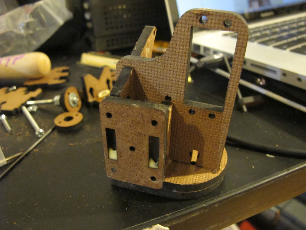
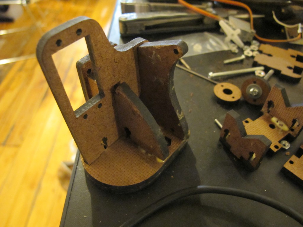
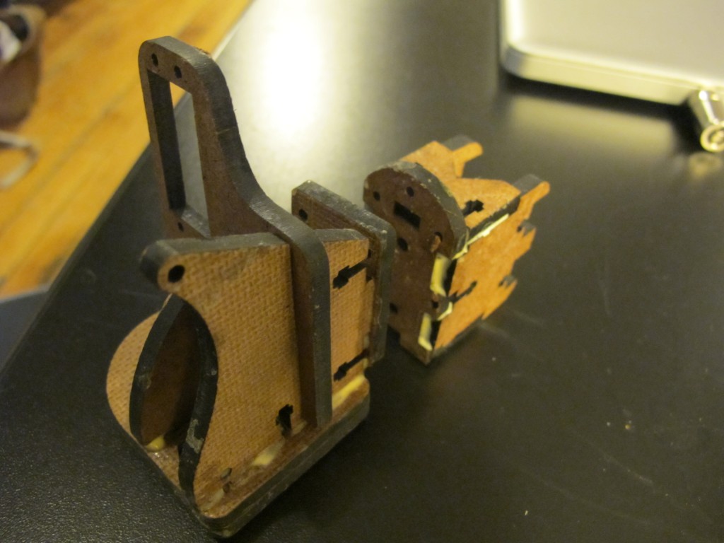
I made a prototype, based on MakerBot’s Unicorn PenPlotter, of a servo mechanism that will move vertically in linear motion:
Then we modified it to look simpler :


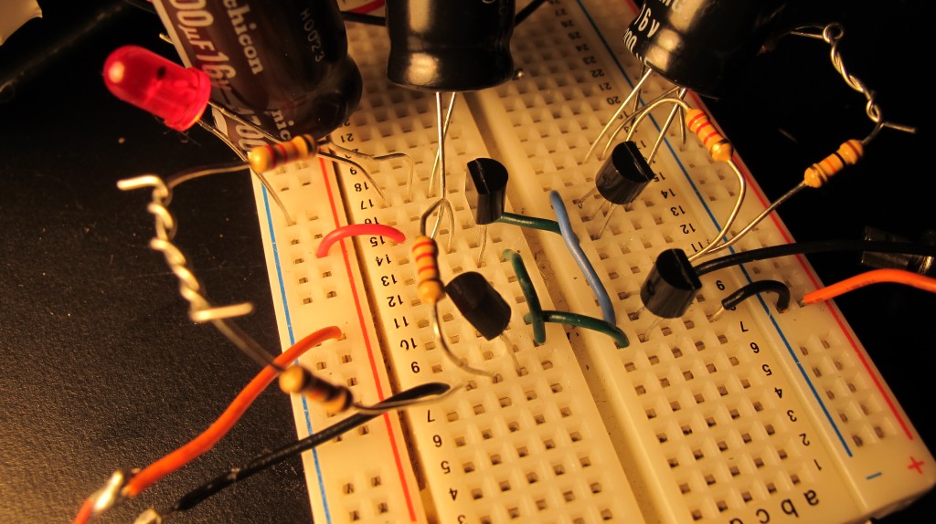
The circuit:

At first we thought we could use the solar kit to charge a 12V solenoid, which would, through arduino, read our data of solar light levels over the past month, and pulse an electromagnetic field through ferrofluid, thereby mapping our data at a condensed temporal resolution. However, although the solar kit has a 12 V battery, we were not getting nearly enough response from the solenoid because, perhaps, the charge controller limits the current? (I need to think through this more)


We also tried using different beam circuits to store voltage in capacitors then to discharge, pulsing a solenoid. Similarly, we could not quite get enough current.
We had a bit of trouble reading through the data from our micro SD card – We switched to the adafruit sd Card shield, and I think we might have been choosing the wrong chip Select pin? we couldn’t figure out why the file DATA.TXT was not opening correctly. After a while, we switched back to the sparkfun shield or the card reader, and it worked fine.
This is the code we practiced with, but later we got the data on the SD card to read directly onto the arduino (see below)
#include <Servo.h>
int changer = 1;
 int incomingData;//variable to read incoming data
Servo myservo;  // create servo object to control a servo
                // a maximum of eight servo objects can be created
 int servoState;
 int prevState;
  const int transistorPin = 9;    // connected to the base of the transistor

int pos = 0;    // variable to store the servo position
int myData[] = {1,2,3,4,5,6,7,8,9,10,11,12,13, 13,13,13,13,13,13,13,13,13,13,12,11,10,9,8,7,6,5,4,3,2,1};// = new Array[12];//1,myData2;


void setup()
{
    Serial.begin(9600);
       pinMode(transistorPin, OUTPUT);
  myservo.attach(9);  // attaches the servo on pin 9 to the servo object
Serial.print("Servo Data Test!!");

 }

void loop()
{


       for(int i=0;i<29;i=i++){
         if(i>12 || i<=1){changer*=-1;}
       int intt=map((myData[i]*20),0,20*13, 180,70);
       int solenoid = map((myData[i]*20),0,20*13, 700,1023);
          analogWrite(5, solenoid);
        myservo.write(intt);
       delay(50);
       }
  }
We are using the Sparkfun data logging shield
//CS pin : 8; VCC/GRNd; DO pin 12; DI pin 11
//using the sparkfun microsd data logger, (or the shield); writes millis and time in secs

#include <SdFat.h>
#include <SdFatUtil.h>
#include <ctype.h>

//Create the variables to be used by SdFat Library

Sd2Card card;
SdVolume volume;
SdFile root;
SdFile file;
 const int transistorPin = 5;    // connected to the base of the transistor
  int potValue1 = 0;               // value returned from the potentiometer
#include <Servo.h>
char name[] = "DATA.TXT";     //Create an array that contains the name of our file.

char contents[256];           //This will be a data buffer for writing contents to the file.
char in_char=0;
String line;
int index=0;                  //Index will keep track of our position within the contents buffer.
Servo myservo;  // create servo object to control a servo
void setup(void)

{
    Serial.begin(9600);        //Start a serial connection.
       pinMode(transistorPin, OUTPUT);
    pinMode(8, OUTPUT);       //Pin 10 must be set as an output for the SD communication to work.
    card.init();               //Initialize the SD card and configure the I/O pins.
  myservo.attach(9);  // attaches the servo on pin 9 to the servo object
    volume.init(card);         //Initialize a volume on the SD card.
    root.openRoot(volume);     //Open the root directory in the volume.
}
void loop(void){
   // file.open(root, name, O_CREAT | O_APPEND | O_WRITE);    //Open or create the file 'name' in 'root' for writing to the end of the file.

    //sprintf(contents, "Millis: %d    ", millis());    //Copy the letters 'Millis: ' followed by the integer value of the millis() function into the 'contents' array.
    //file.print(contents);    //Write the 'contents' array to the end of the file.

 // file.close();            //Close the file.

 file.open(root, name, O_READ);    //Open the file in read mode.
    in_char=file.read();              //Get the first byte in the file.
    //Keep reading characters from the file until we get an error or reach the end of the file. (This will output the entire contents of the file).

    while(in_char >=0){            //If the value of the character is less than 0 we've reached the end of the file.
        Serial.print(in_char);    //Print the current character
        //line = file.read();//read each line?
       // Serial.println(line);

       in_char=file.read();      //Get the next character


        float newFloat = map(in_char, 0,9,0,180);

        myservo.write(in_char);
        float solin_char= map(in_char, 0,9,500,1023);
        analogWrite(5, solin_char);
        delay(300);


    }
    file.close();    //Close the file
    //delay(1000);     //Wait 1 second before repeating the process.
}
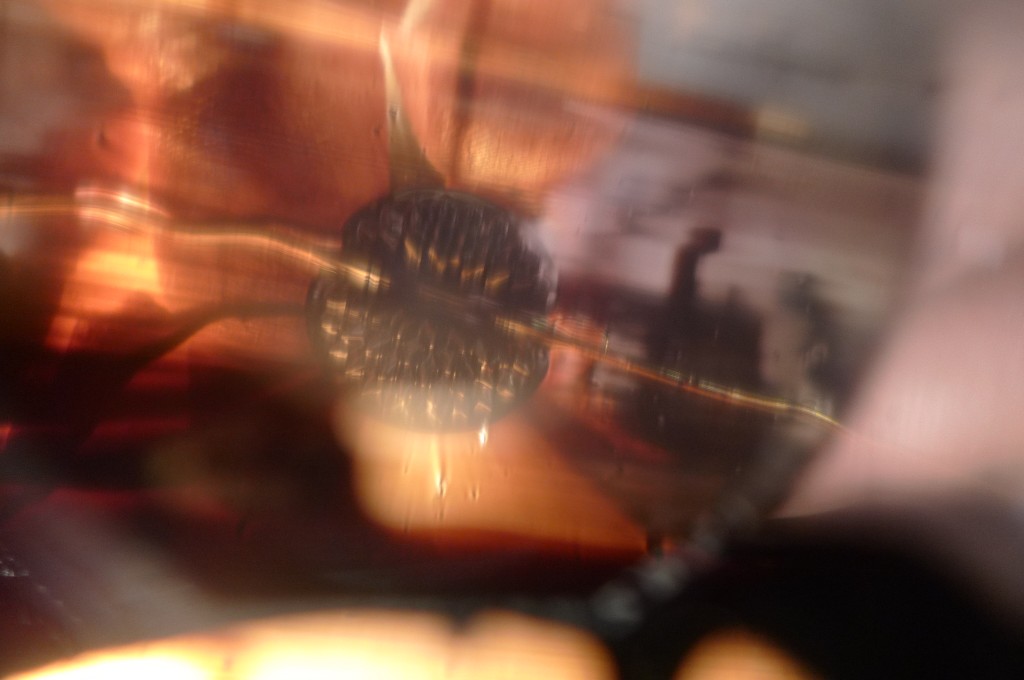
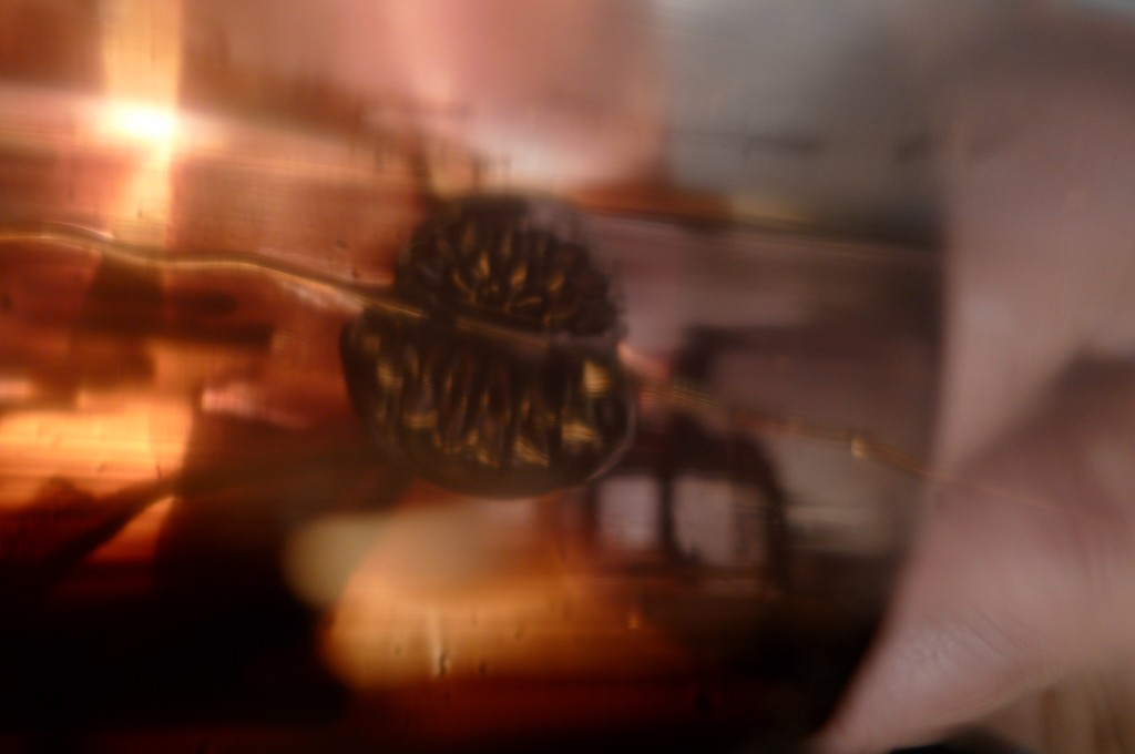
Some more videos of progres and the mechanism:
more with Ferrofluid and Solar Energy
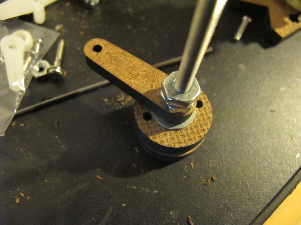
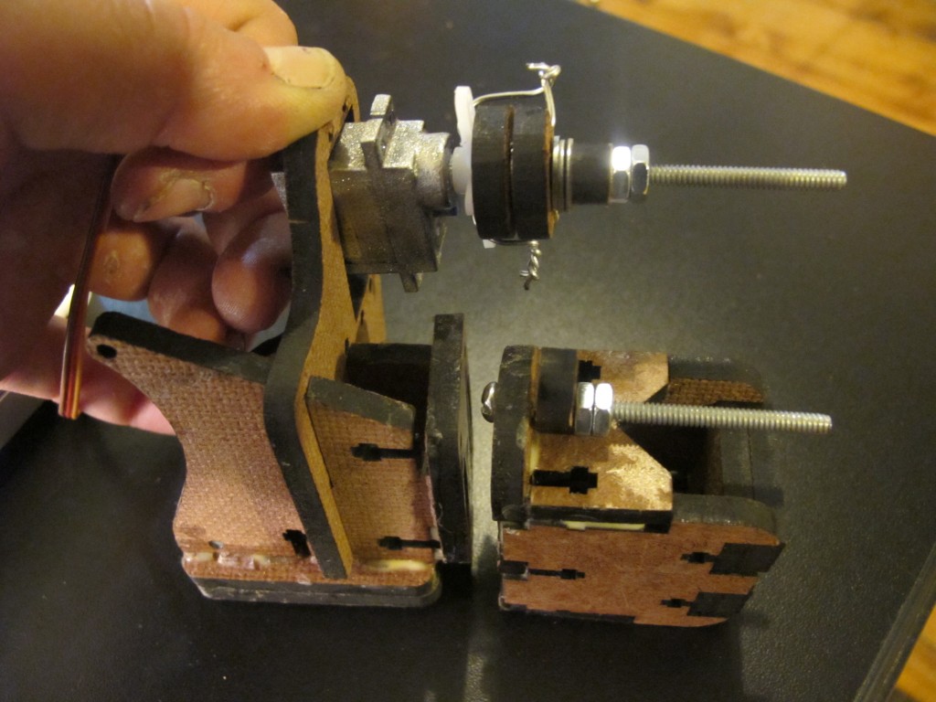
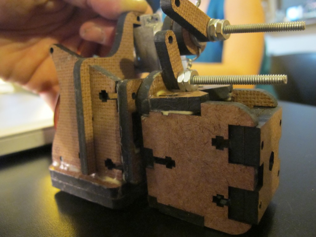
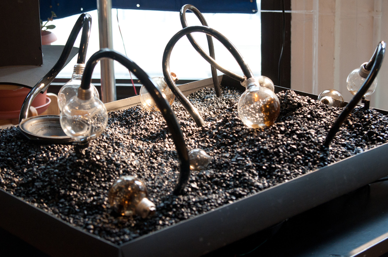
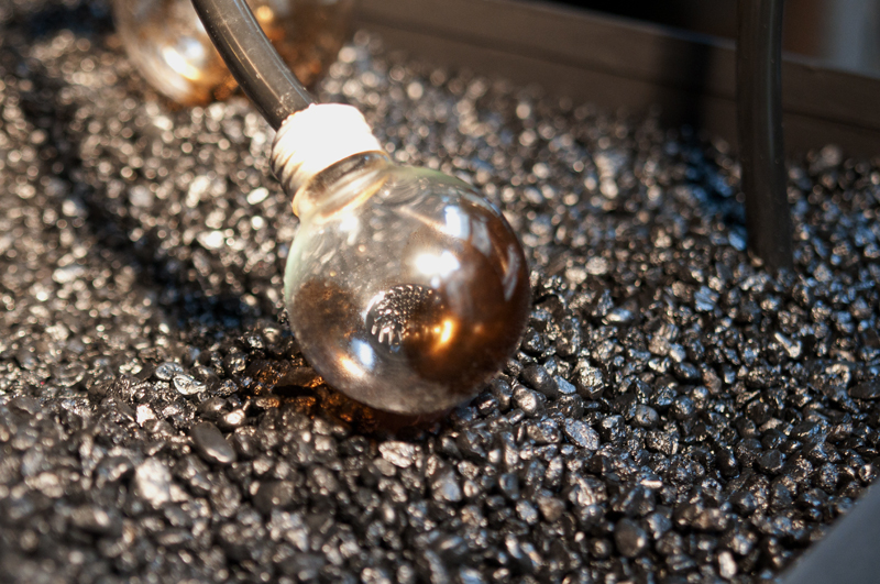
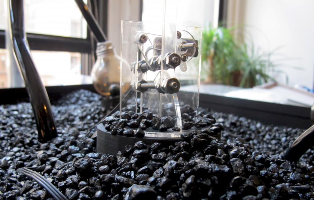
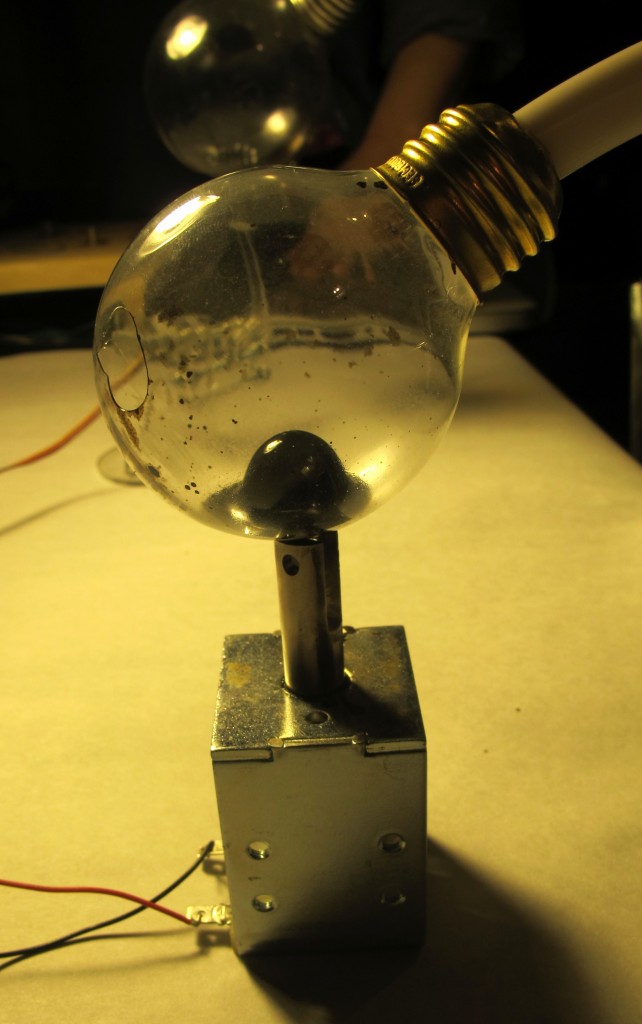
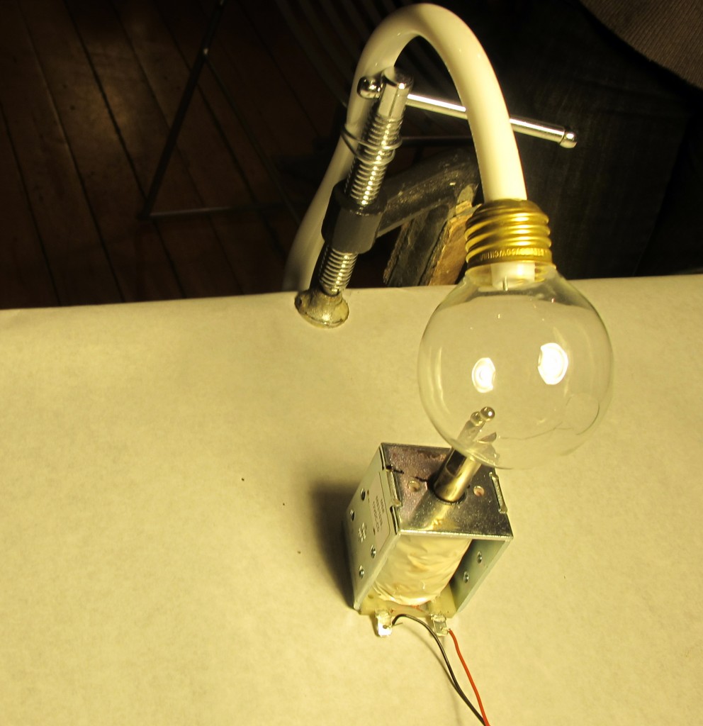
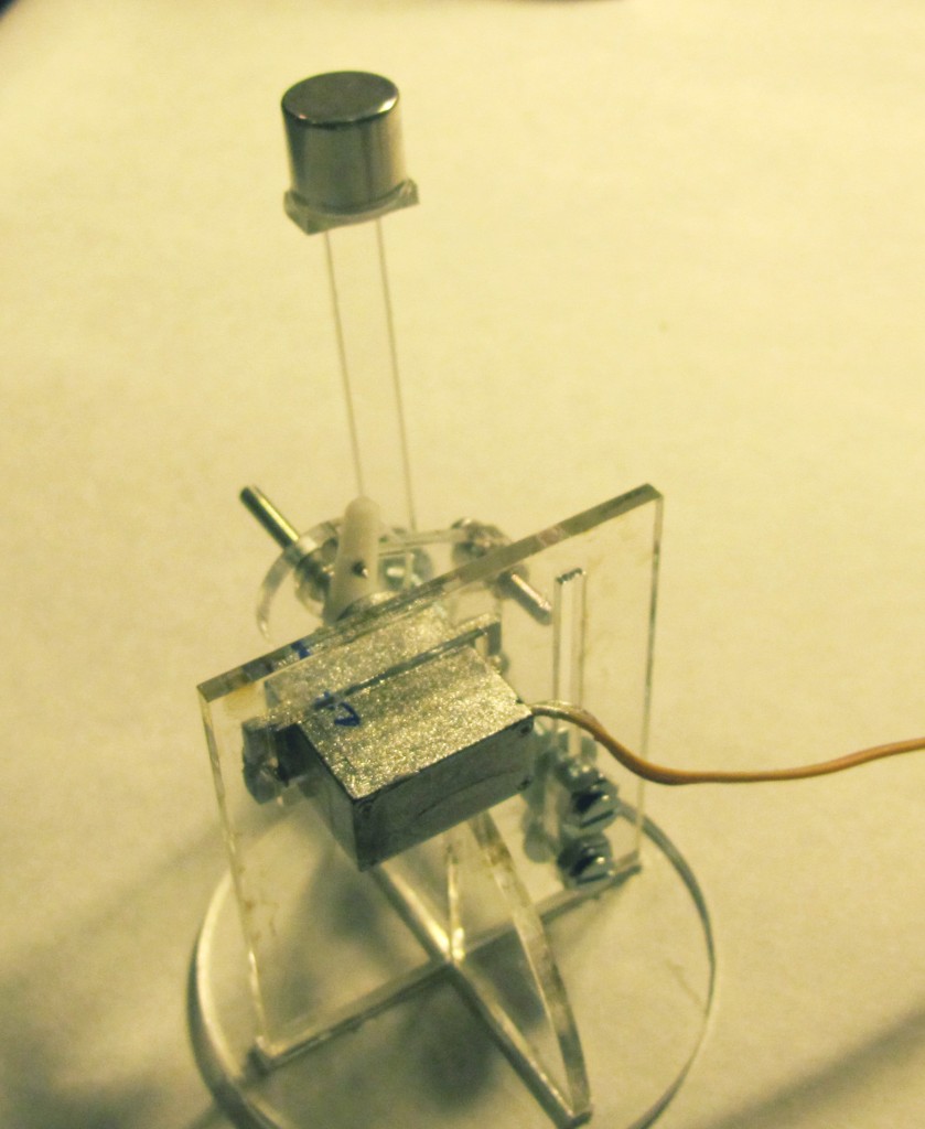
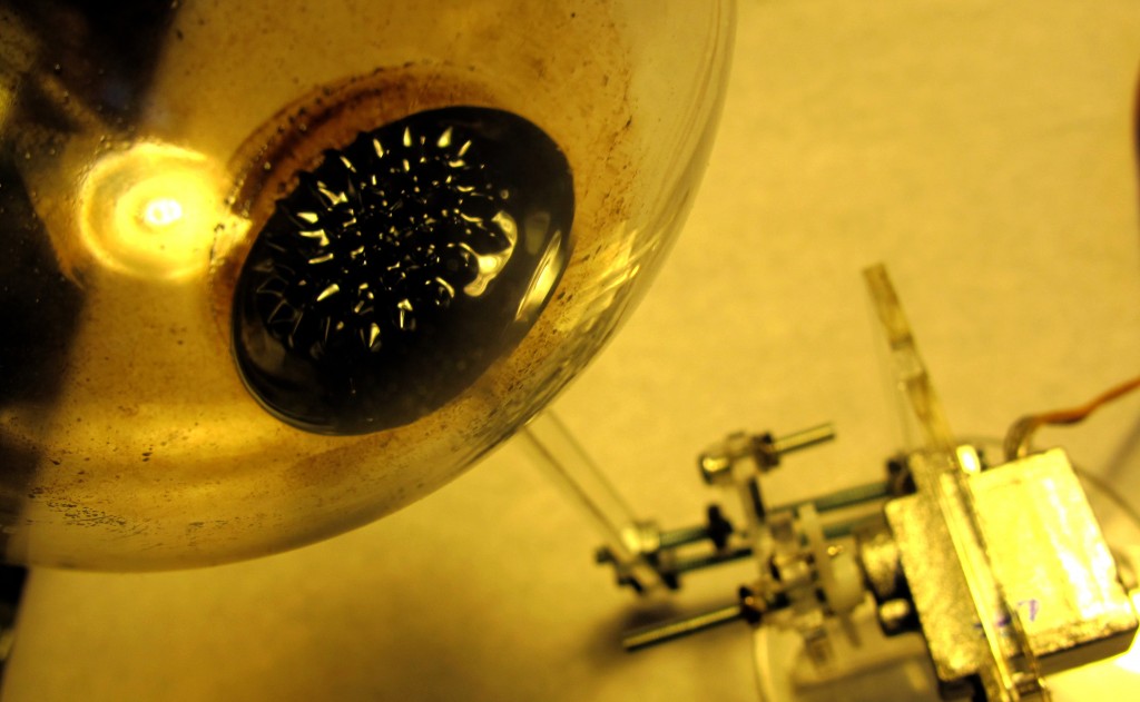
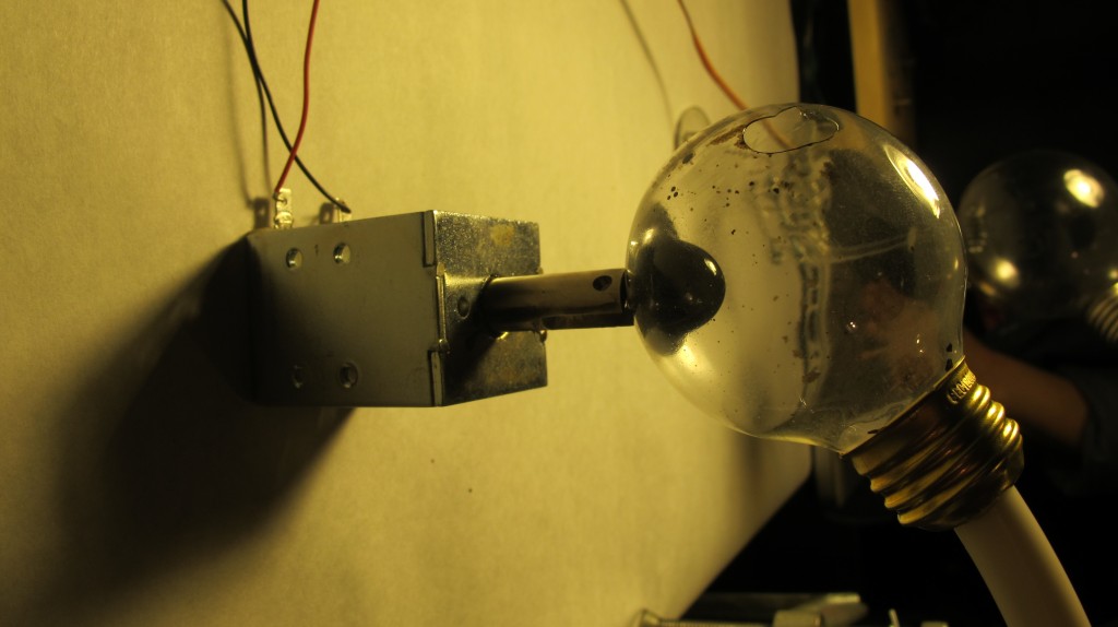
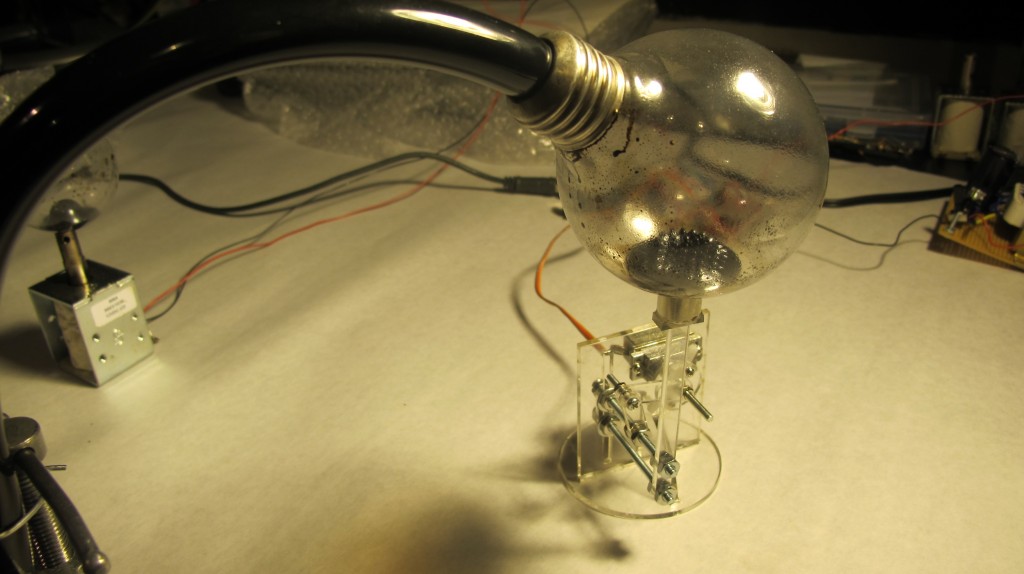
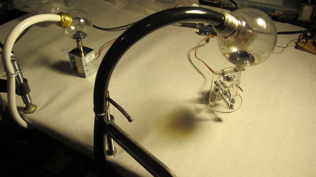
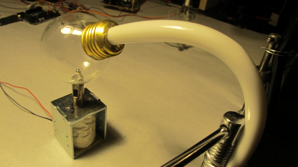
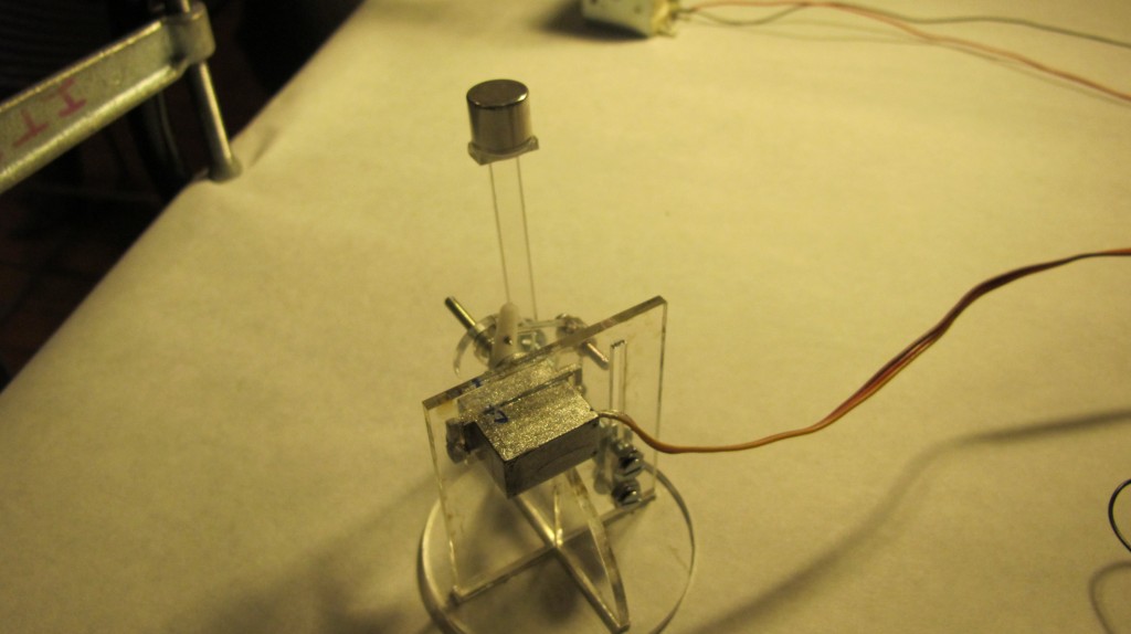
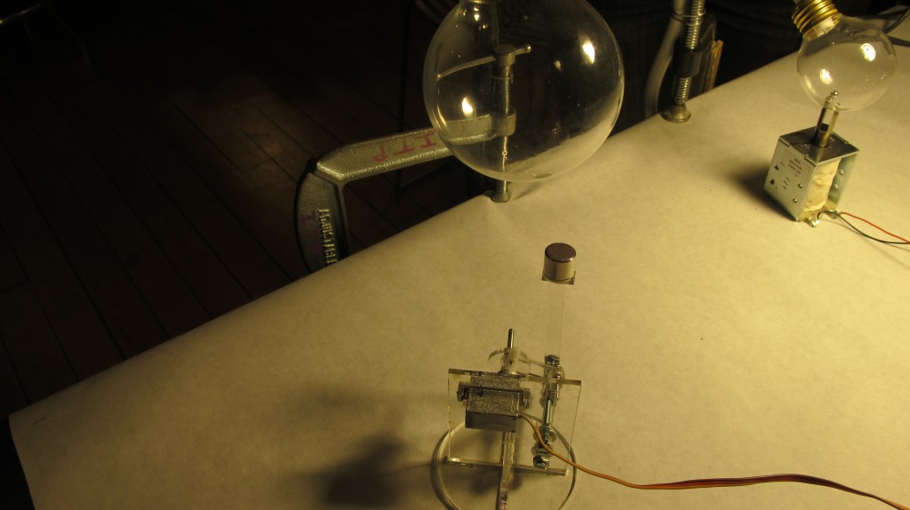
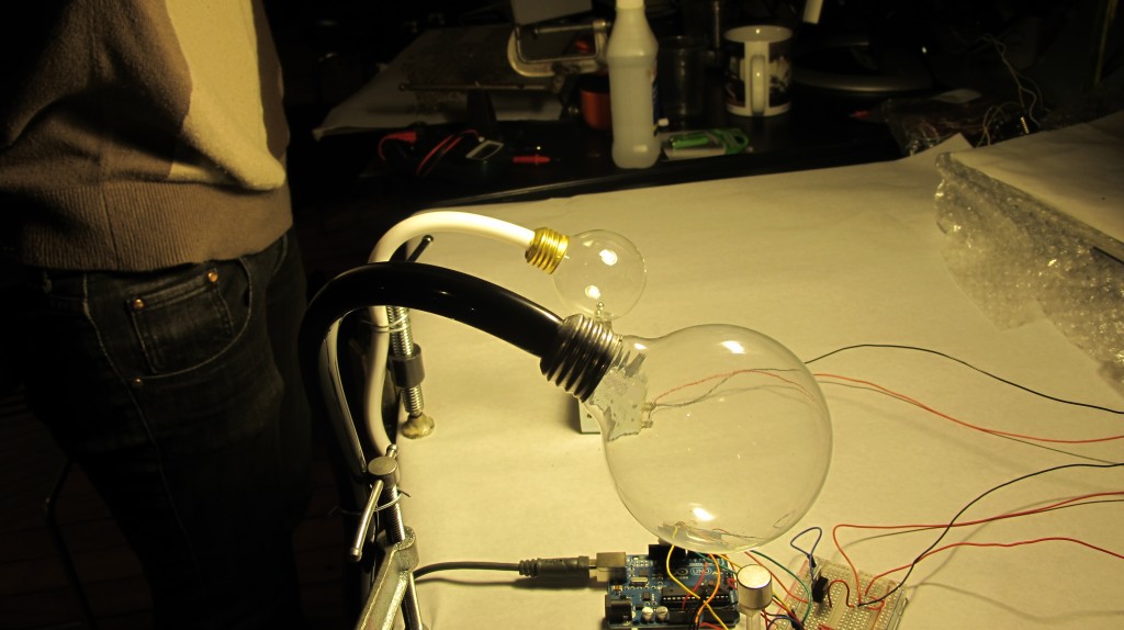
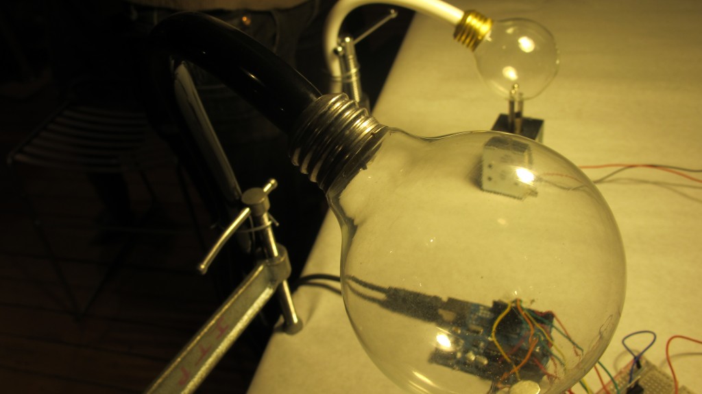
Using the MakerBot Unicorn PenPlotter as a guideline for a mechanism that uses a servo to laterally back and forth along a single axis, I made a mechanism that oscillates the proximity of a rare earth magnet back and forth in the proximity of ferrofluid. We are iterating through our collected data, to visualize and graph energy and weather data we are collecting over the month, in the planar layer of ferrofluid.
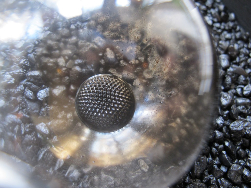
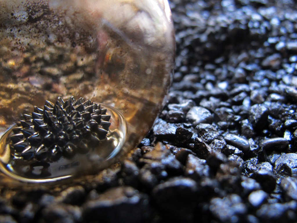
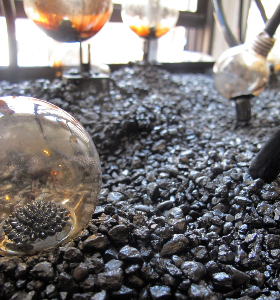
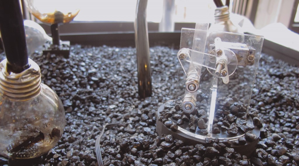
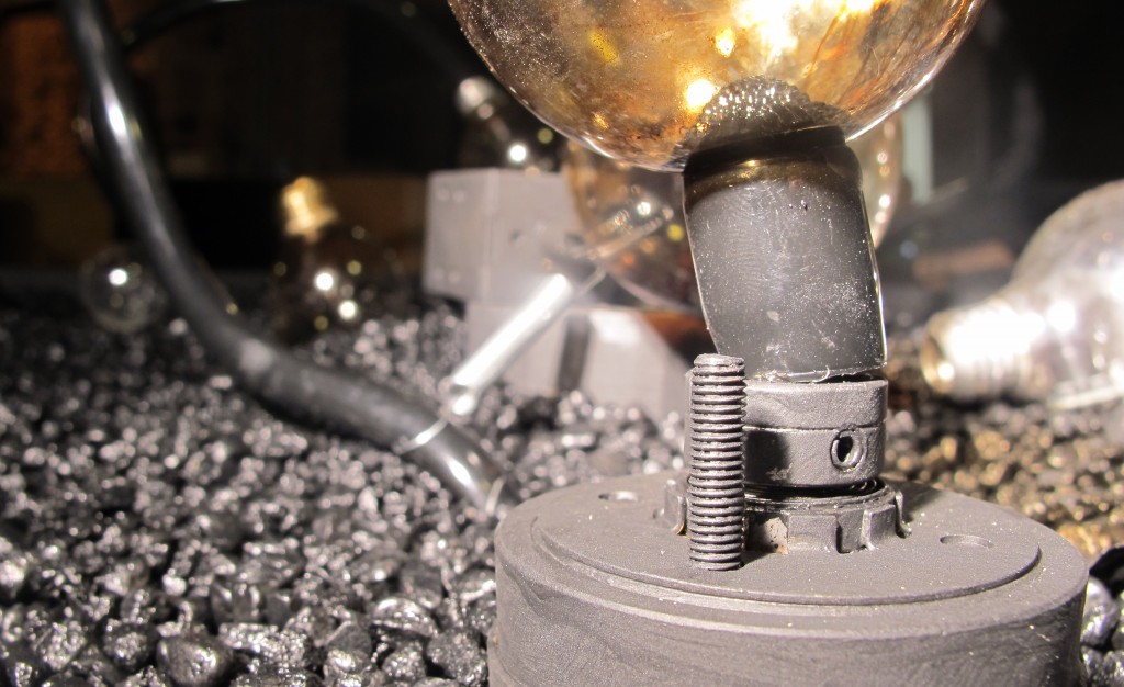
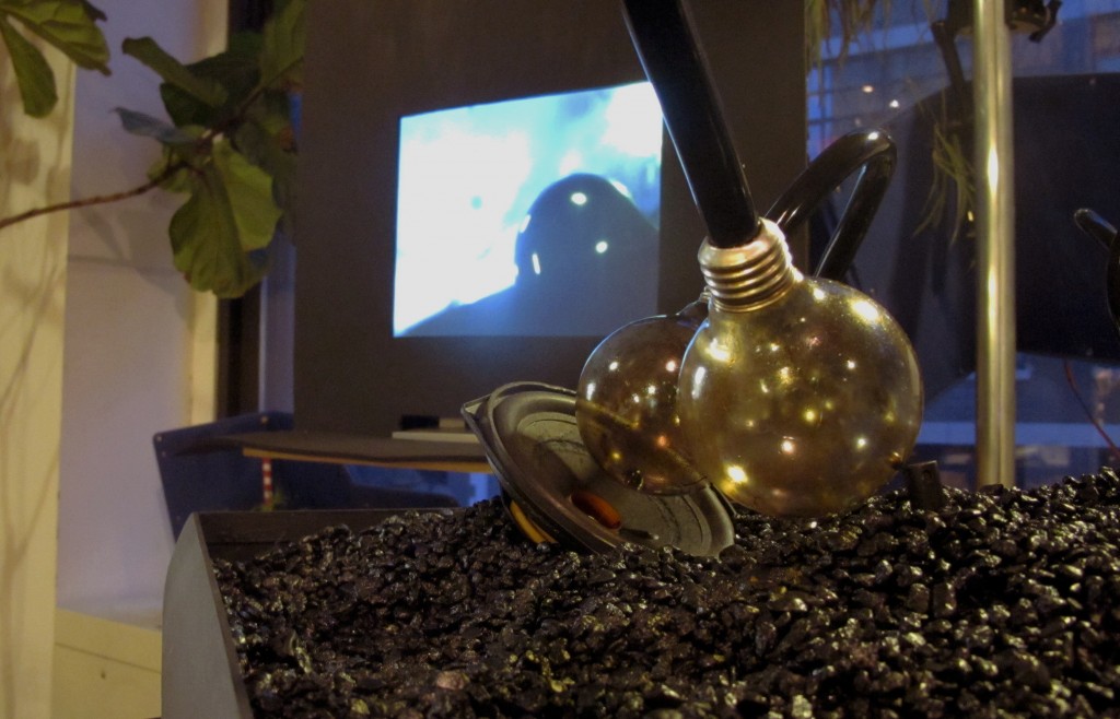
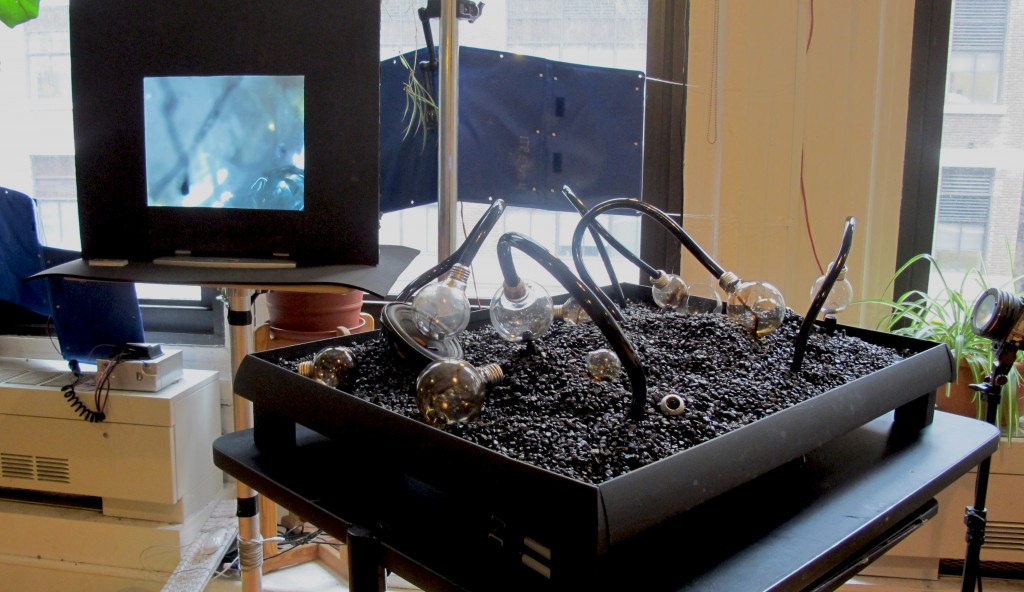
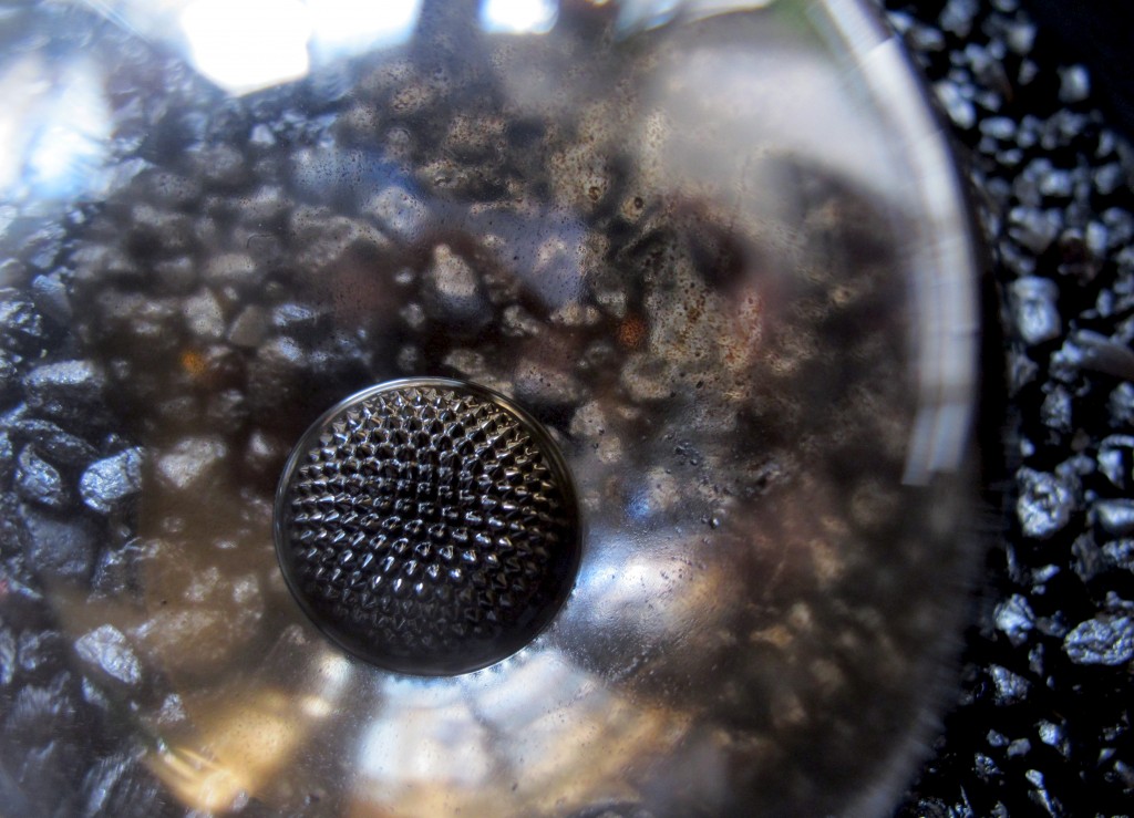
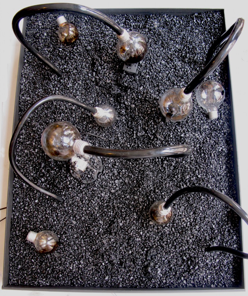
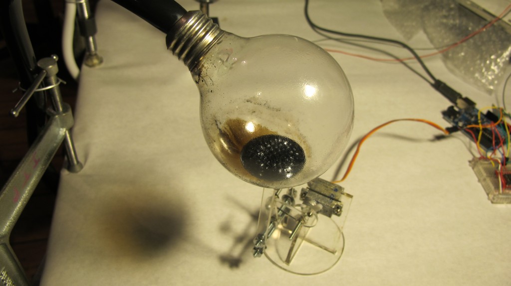
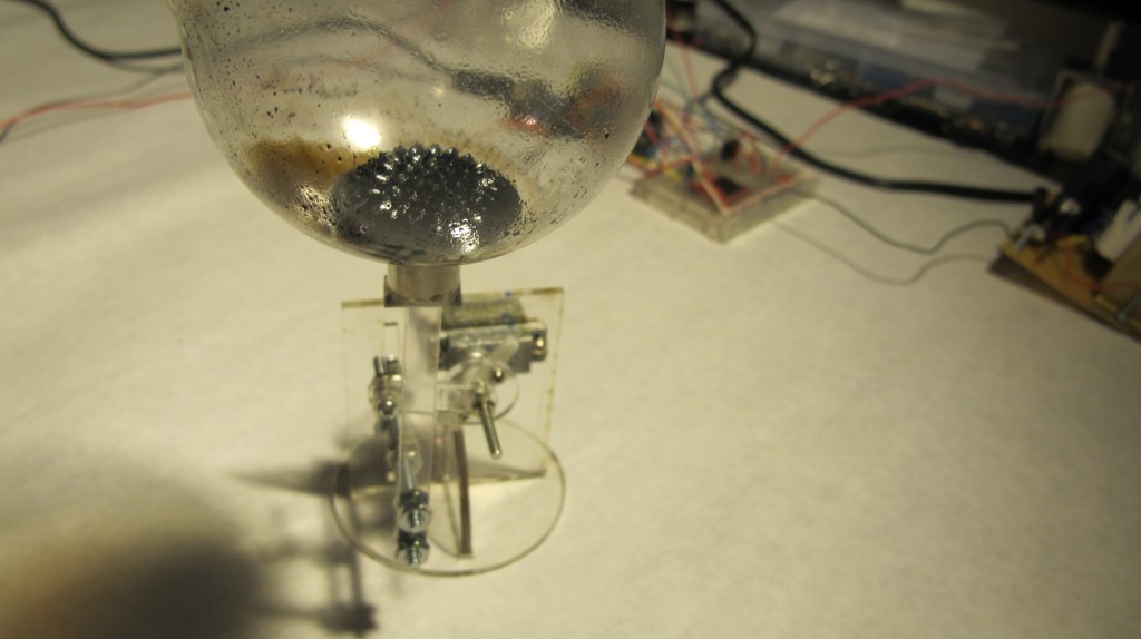
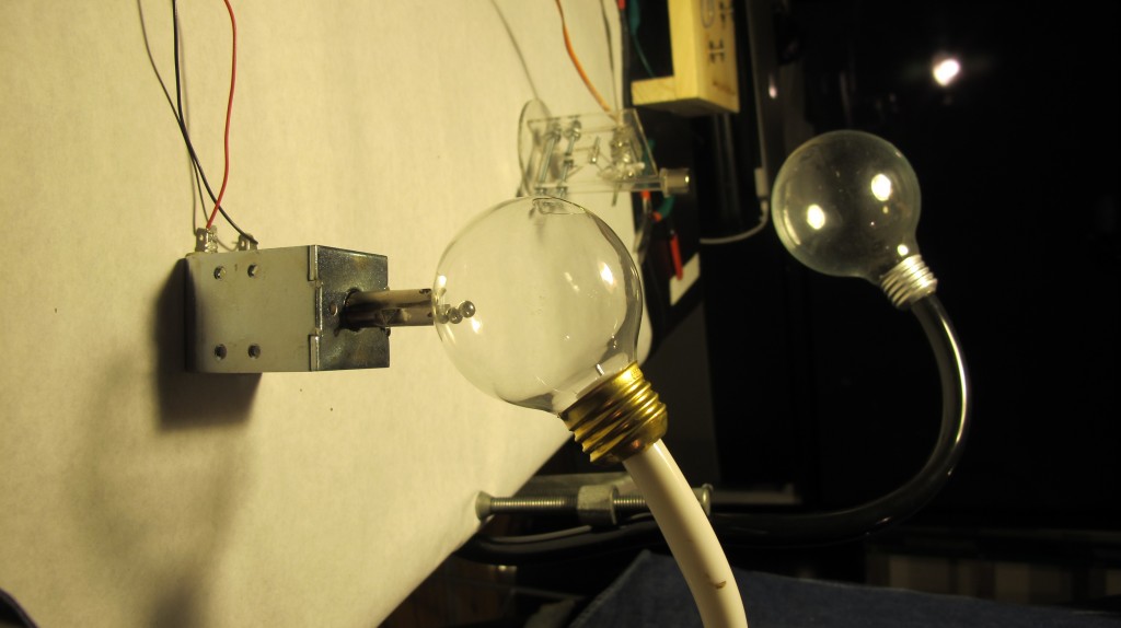
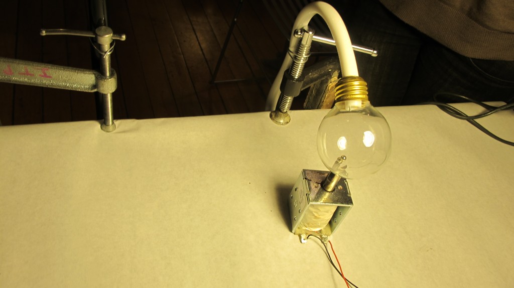
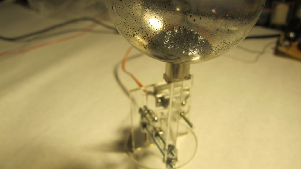
We hollowed out lightbulbs in order to cheaply make small terrariums for units that contain ferrofluid and a couple magnets, that will be perched atop solenoids and magnets.
I used a linear slide from a chain lock to keep the arm holding the magnet in place. The pieces are drying over night


The data logging is going well – although every now and then when I check the card, it didn’t read the data (I think I have to unplug the arduino each time. Oh, and in case I forget, it took me two days to realize that with the data logger and RTC to work, I need at least 8V from a wall wort (from the 5V one we were getting 0/0/0 for the date / time. (Also, I switched the code so we it is always writing to data.txt as opposed to a new file each time, so it will be much easier to graph (instead of copying and pasting from different text files, we can just use data.txt in processing).
We also thought that because the solenoid was working with 12V from the bench power supply, we would be able to use the 12V battery powered off the solar kit / charge controller at school – However, when we plugged in the solenoid to the 12 V battery…. turned out, it hardly worked. And the voltage reading was about 0.7… RIGHT….
ferrofluidic motor syringe
continuing with the ferrofluid idea:
so my servos are strong enough to push syringes with liquid:
I got inspired by a radial engine:
and was going to start off by building a piston:
But I have a bunch of servos, so I decided to model some sort of an improvised two-cylinder piston that takes in fluid and spits it back out, that is modelled after MakerBot’s Unicorn Pen plotter – An elbow pushes back and forth laterally

I think that I am going to do some 3d moving model using ferrofluid, perhaps using the data that Genevieve and I are collecting about solar / temperature data
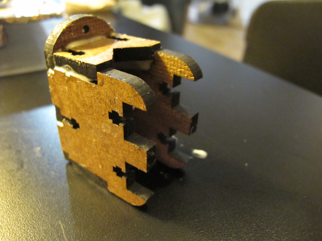
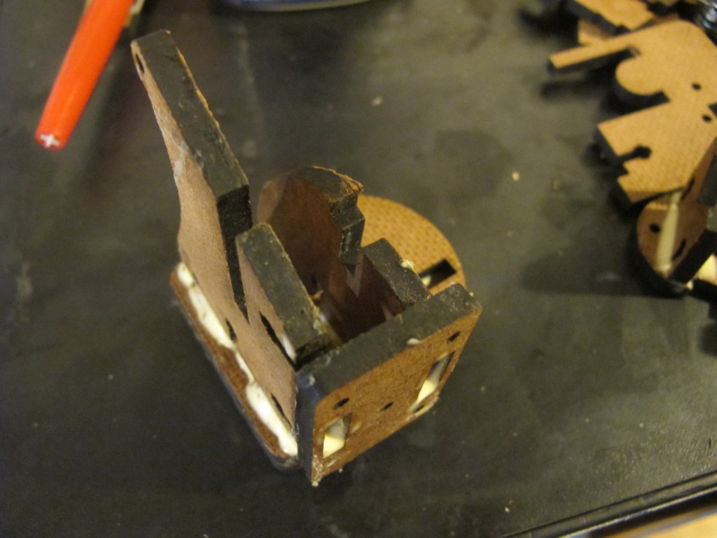
So, using the makerBot wiki, I got a pattern to cut the pieces for the mechanism: I cut it in both masonite and clear plexi (I assume the plexiglass is stronger but I preferred the transparent aesthetic, so I’ll try it!)….

now, to get some nuts and bolts…
logging the data
14.38, 2.52
with the solar panels in, we’re 17, 3
click to see more info
-

- April 10
-

- April 13

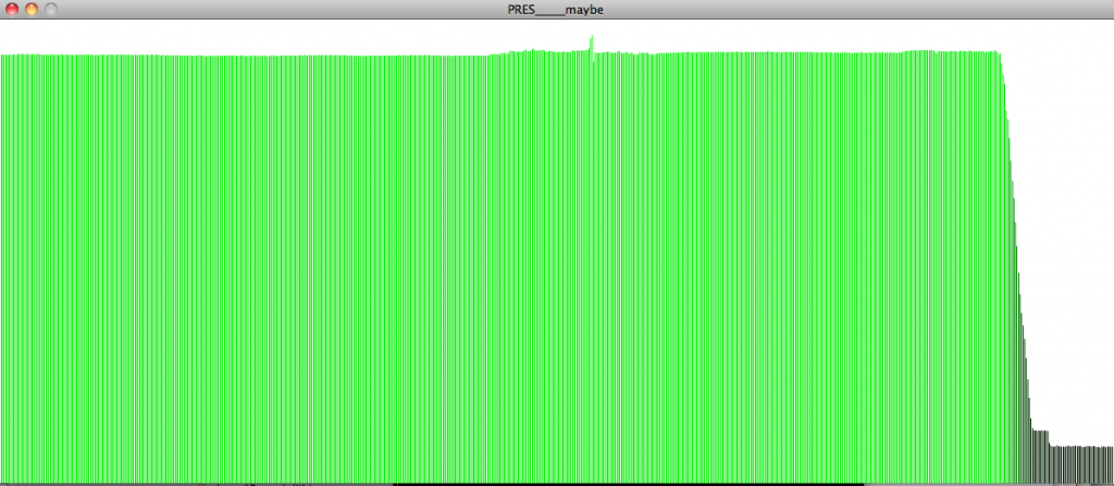
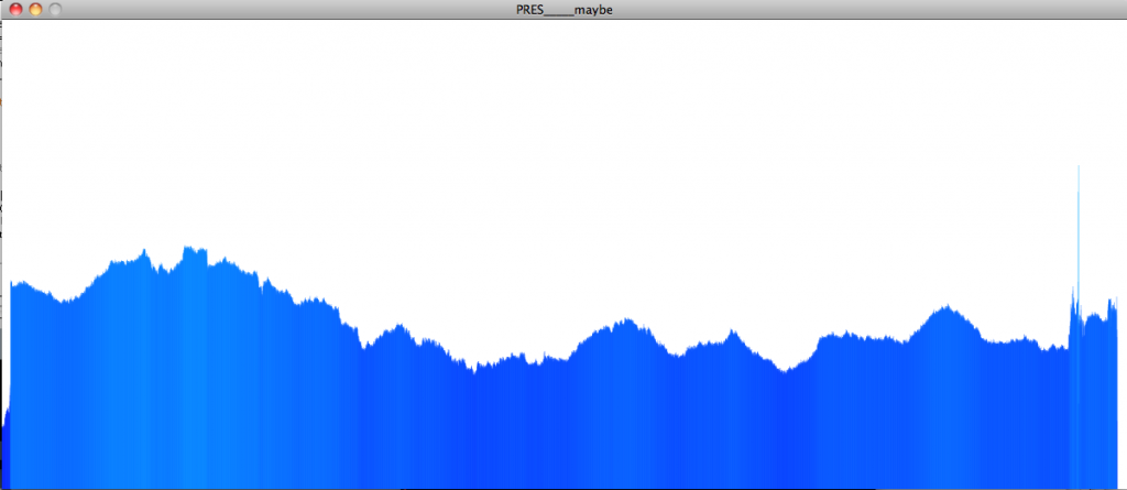
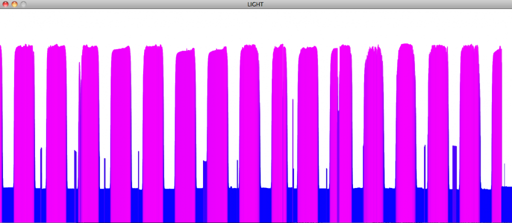
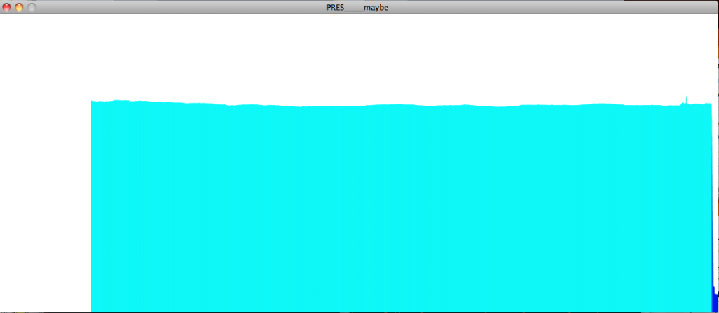
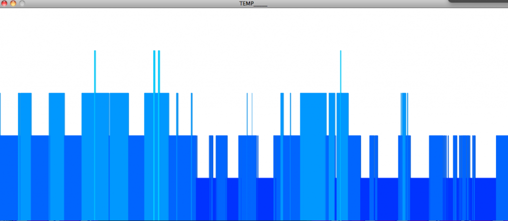
logging solar data
Genevieve and I now decided to log data from the sun over the course of the month – most likely, voltage, and light level. We will use both a photocell and two large solar panels (during the day one gave about 20 V). (And of course, we will power the arduino sustainably!)
We are using a RTC (real time clock from adafruit), a micro sd card data shield, and the following code (derived from Tom Igoe’s github)
Here is the circuit:

With a 9 V battery plugged in for a few minutes, this is the result (reading voltage once per minute):


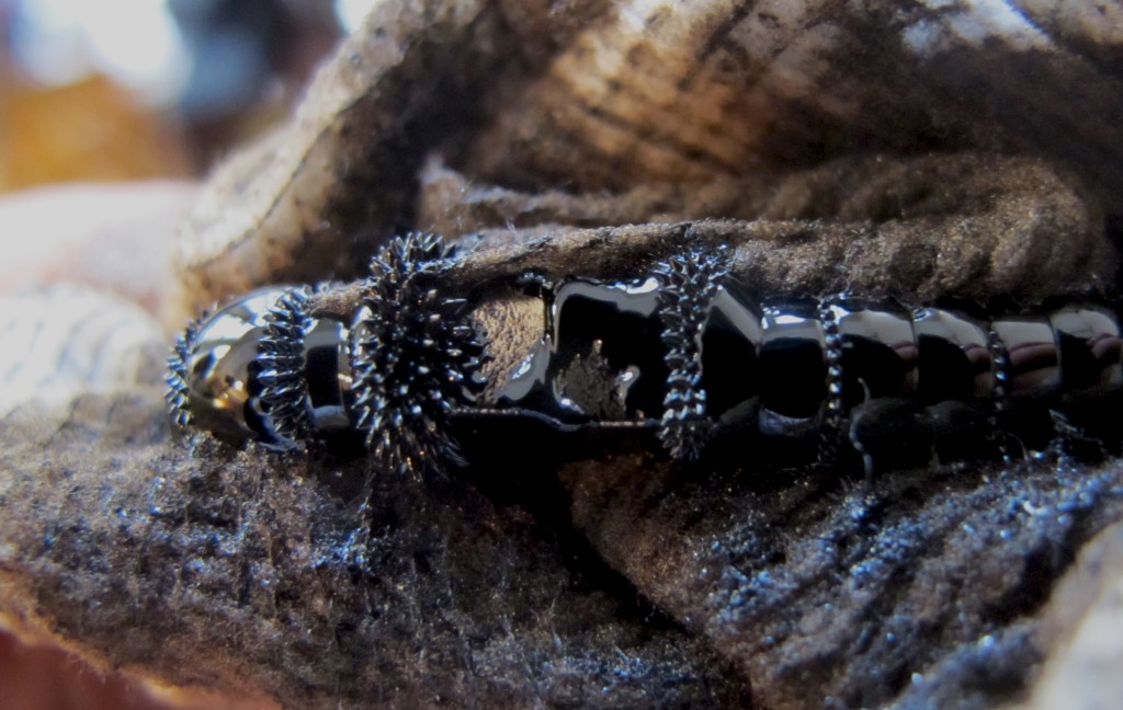
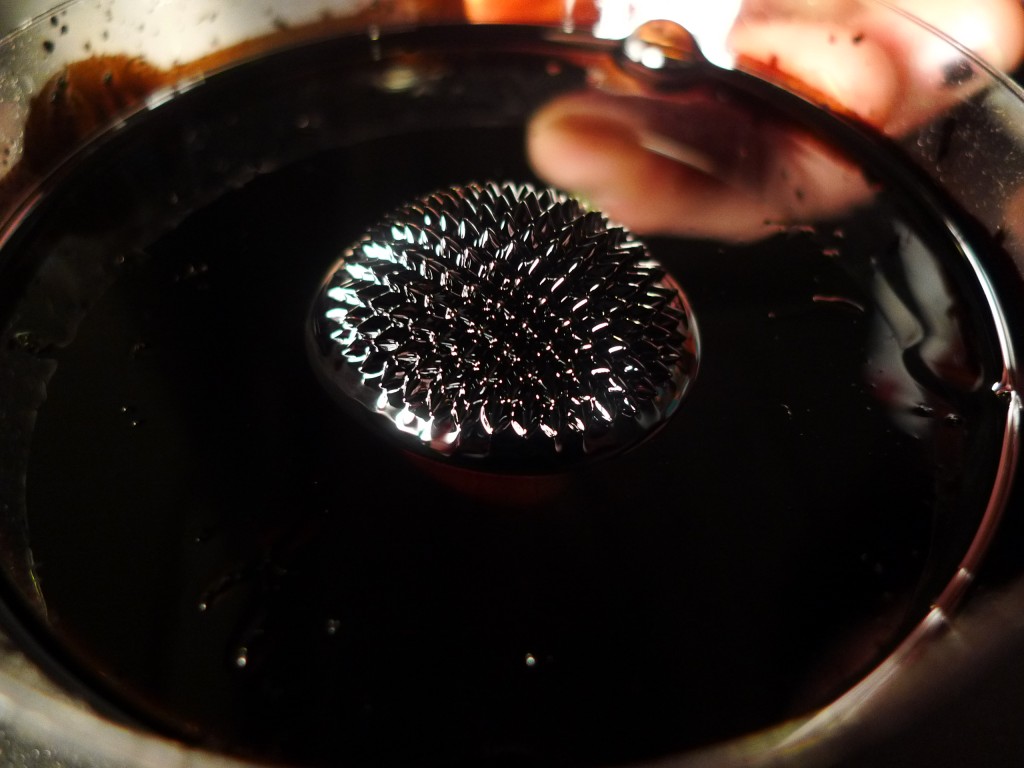
Ferrofluid, and more…

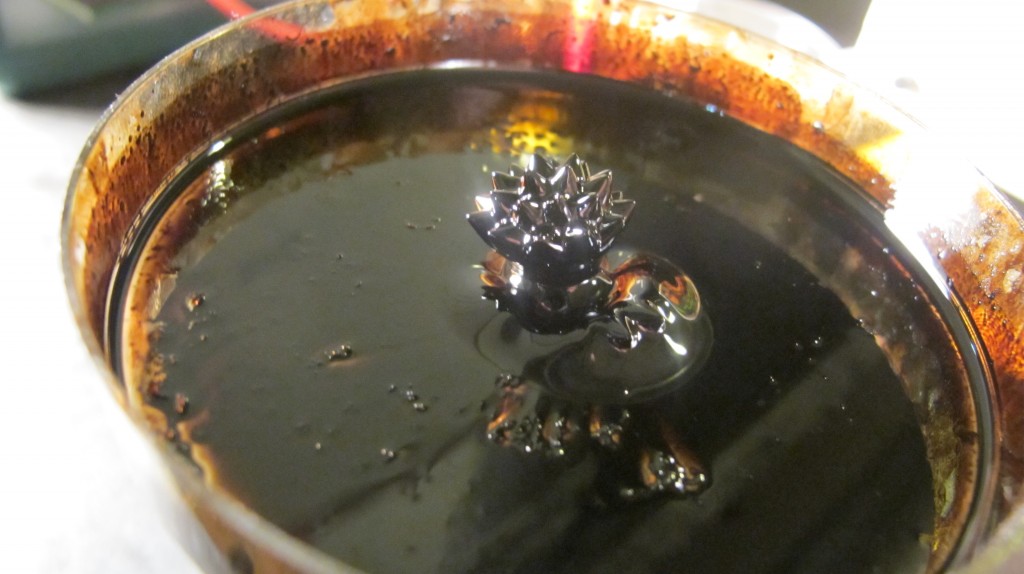
Genevieve and thought about building solar powered ferrofluidic sculpture. So we started to play around with ferrofluid – and made a mess. It is cool stuff and can make some beautiful patterns and behavior.
At first we talked about creating a sound with a photocell , using a “light to sound” circuit – The speaker, powered by a solar panel, would create an electromagnetic field, driving cool patterns in ferrofluid….
well, electromagnets aren’t THAT easy…
a light to sound circuit:

So we have since modified our plan, after many iterations… I think we will log voltage and light input over the course of the month, and do something cool with that data (a ferrofluid-type graph?)
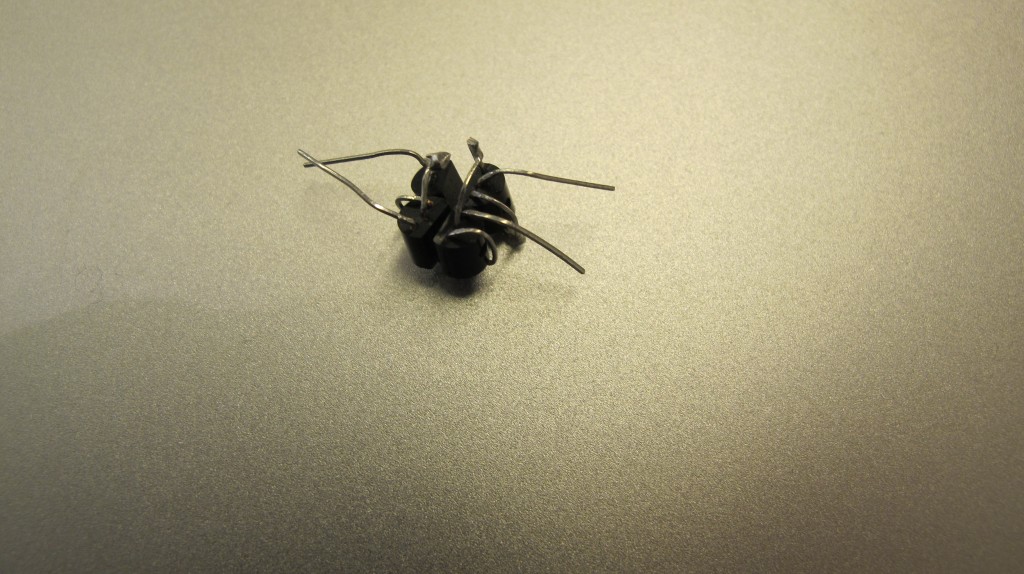
We are still hooked on the electromagnet idea and have played around with some (a nail with a coil, a few solenoids) to see what type of voltage we need to input in order to get some interaction with the ferrofluid
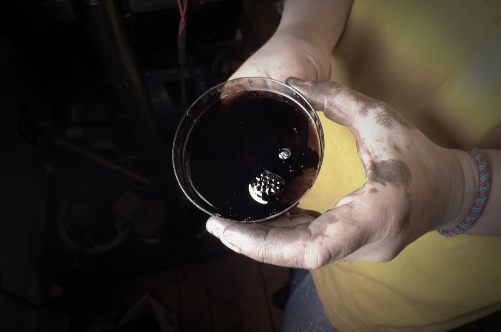
MAGNETIC EXPLOSION:
after the mess:
RWEL – smtp and IMAP libraries
I used this code to send an email:
import smtplib

fromaddr = 'gabriella.levine@gmail.com'
toaddrs  = 'gabriella.levine@gmail.com'
msg = 'There was a terrible error that occured and I wanted you to know!'

# Credentials (if needed)
username = 'gabriella.levine@gmail.com'
password = 'qwewqwe1!'

# The actual mail send
server = smtplib.SMTP('smtp.gmail.com:587')
server.starttls()
server.login(username,password)
server.sendmail(fromaddr, toaddrs, msg)
server.quit()
I would like to be able to monitor a project I’m doing for Sustainable energy (where I will be monitoring the voltage input from a solar panel), and send myself an email if any of the components (the Arduino, the Xbee, the Real time clock, the sd card / shield) stops functioning properly
I thought using this code and the smtp library would send an email but I KEEP getting an error(see below), and I’m not quite sure why yet:
import smtplib
from email.mime.text import MIMEText
sender = 'gabriella.levine@gmail.com'
recipients = 'gl715@nyu.edu'
msg = MIMEText('hi my name is gabby')
msg['Subject'] = 'test'
msg['gabriella levine'] = sender
msg['you'] = recipients
smtpserver = 'smtp.gmail.com'
smtpuser = 'gabriella.levine' # set SMTP username here
smtppass = 'qwewqwe1!' # set SMTP password here
session = smtplib.SMTP(&amp;amp;amp;quot;smtp.gmail.com&amp;amp;amp;quot;, 587)
session.ehlo()
session.starttls()
session.ehlo()
session.login(smtpuser, smtppass)
smtpresult = session.sendmail(sender, [recipients], msg.as_string())
if smtpresult:
errstr = &amp;amp;amp;quot;&amp;amp;amp;quot;
for recip in smtpresult.keys():
errstr = &amp;amp;amp;quot;&amp;amp;amp;quot;&amp;amp;amp;quot;Could not delivery mail to: %s
Server said: %s
%s
%s&amp;amp;amp;quot;&amp;amp;amp;quot;&amp;amp;amp;quot; % (recip, smtpresult[recip][0], smtpresult[recip][1], errstr)
raise smtplib.SMTPException, errstr
session.close()
ERROR:
Traceback (most recent call last):
File “1151.py”, line 1, in
import smtplib
File “/System/Library/Frameworks/Python.framework/Versions/2.6/lib/python2.6/smtplib.py”, line 46, in
import email.utils
File “/Users/administrator/Desktop/pyEmail/email.py”, line 25, in
conn.login( “putemailhere”, “putpasswordhere” )
File “/System/Library/Frameworks/Python.framework/Versions/2.6/lib/python2.6/imaplib.py”, line 501, in login
raise self.error(dat[-1])
imaplib.error: [AUTHENTICATIONFAILED] Invalid credentials (Failure)
I also started trying to sort through email using the IMAP library – I haven’t gotten very far, and have to look at the documentation some more, but this is what I have:
import sys
import imaplib


conn = imaplib.IMAP4_SSL("imap.gmail.com", 993)
conn.login('gabriella.levine', 'qwewqwe1!')
output = conn.select("INBOX")
print "new messages", output
#toaddress = msg['to']
#output1 = conn.select("SENT MAIL")
#print output1
output1=conn.select('Sent')
print output1
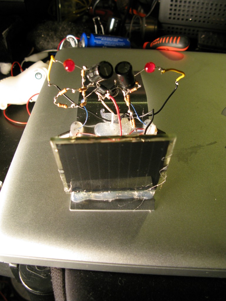
almost finished photopopper


See him moving towards light:
slightly blurry, but you get the idea, maybe
and here again (he falls off the computer
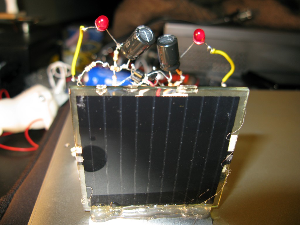

BeamBot
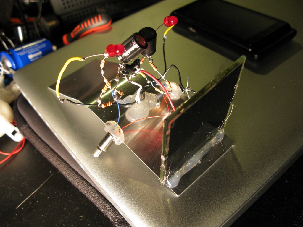
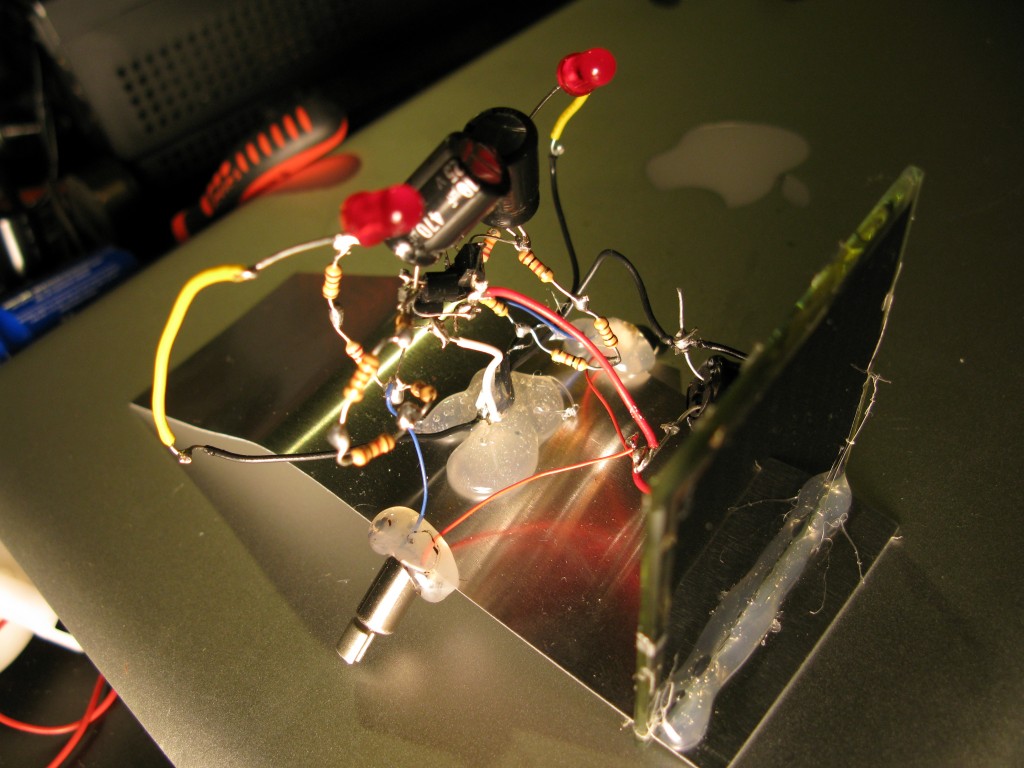
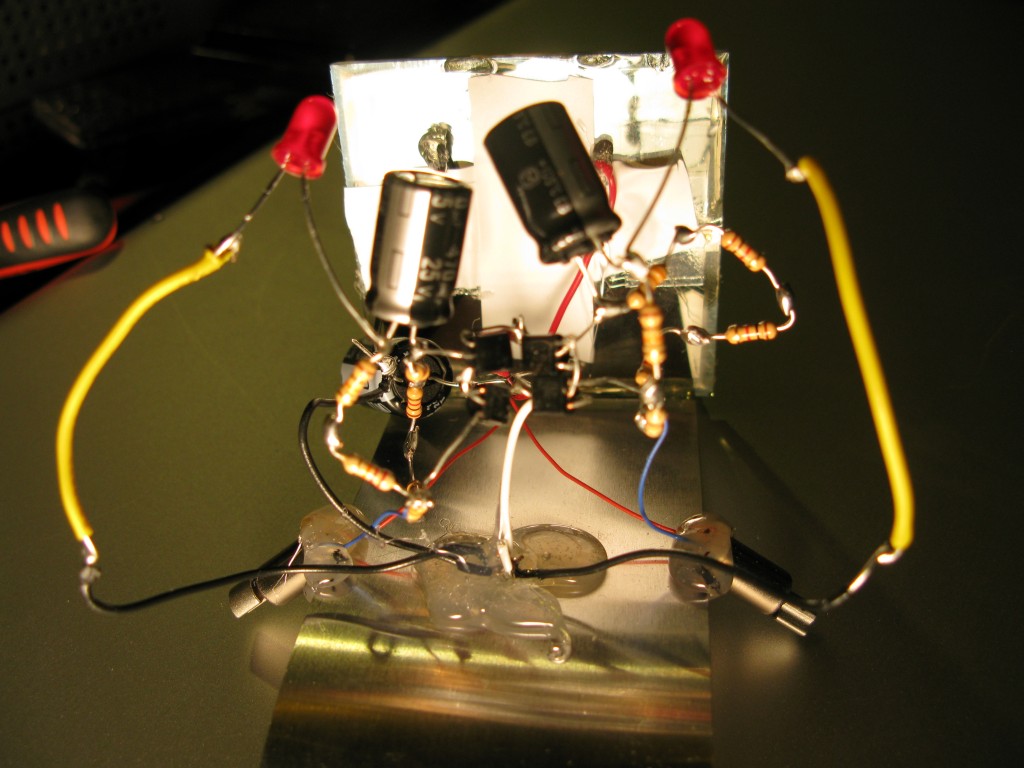
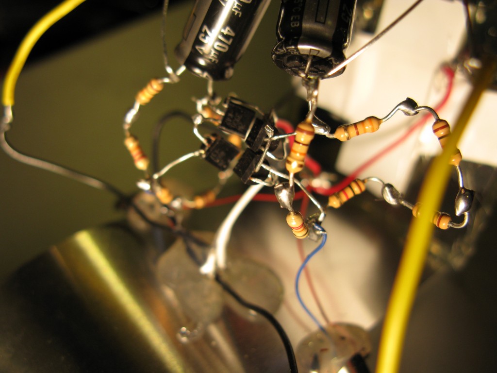
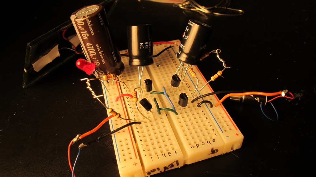
I built the beginning of a BEAM robot: it moves in the light. Using a blinking LED as a diode that allows it to pulse rhythmically. I’m using a small capacitor (2200 uF), but using a clamp light, the solar panel charges to about 4.5 V.
here is my circuit:

I’d like to use an oscilloscope to see more of what’s going on.
I used this circuit from this site

Here are some helpful links for the BEAM photopopper I hope to build:
Solarbotics tutorials
Beam circuits
Fred Photopopper
another Fred Photopopper tutorial
I’d like it to look something like this, and be a smart BEAM (that moves towards the light)

Maybe my BEAM can even have this FM receiver circuit, for, say, a microphone, so it will respond to sound?
kinetic energy HAND POWERED AM receiver
(see project site here)
design by Gabriella Levine, Emily Webster, Genevieve Hoffman

The concept for our Kinetic Energy project evolved from an interest in generating sound by hand. What we ended up creating was an AM frequency receiver that picks up all the frequencies in its bandwidth. It currently doesn’t have tuning capabilities but instead it is sensitive to all frequencies in its immediate vicinity.
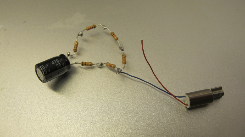
In order to make the receiver we worked from the following circuit to create the portable “radio.” Rather than of using a walkman PCB, though, we chose to substitute the LM380N to amplify the signal.


The most complicated part of the process was generating enough energy to power our circuit by hand. We used a geared stepper motor from a printer as our supply voltage. The stepper motor created a decent amount of AC power but we put the stepper in series to increase the supply and then ran it through a bridge rectifier to convert it to DC power. We used a 2200uf 50V capacitor, large resistors and signal diodes which helped store, smooth and regulate our output voltage.

Our gear box was helpful to increase the revolutions on the stepper but we attempted to attach a pull start to make the revolutions more continuous. The mechanics of attaching the pull start to the gear box proved to be difficult since there aren’t any exposed gears that we could easily attach. We tried to create our own gears but the gears weren’t precise enough to line up with the teeth on the gear box.


We then attached a hand crank which made it easier to turn the crank by hand but wasn’t as continuous a motion as the pull start. We still had trouble making a secure connection between the hand crank and the gear we attached to we, though. This made it difficult to generate as much power as we had hoped for despite trying a variety of capacitors in an attempt to store energy before delivering it to the speaker.

Our ultimate goal is to transmit our own signal and tune the receiver. We’d like to do this on both an AM frequency and also explore the possibilities of transmitting a signal to a TV. Pirate radio/TV!
Sustainable Energy – kinetics

Using this circuit I’m trying to light up an LED by spinning the wheel on my car – HOWEVER, it’s not working. I think I might be doing something wrong with the four diodes I’m using to try to make a full – wave rectifier. I shall later use a multimeter to see where I’m going wrong (as well as calculate the amperage and voltage I’m generating from spinning the wheel)…as well as try it with a single diode as a half-wave rectifier.


