Big Pixel
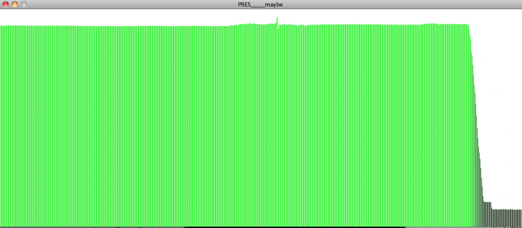
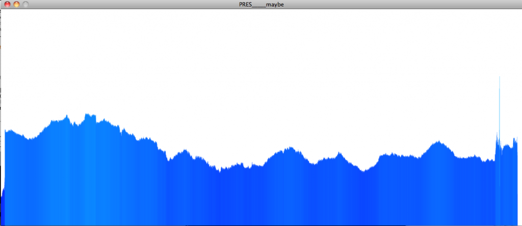
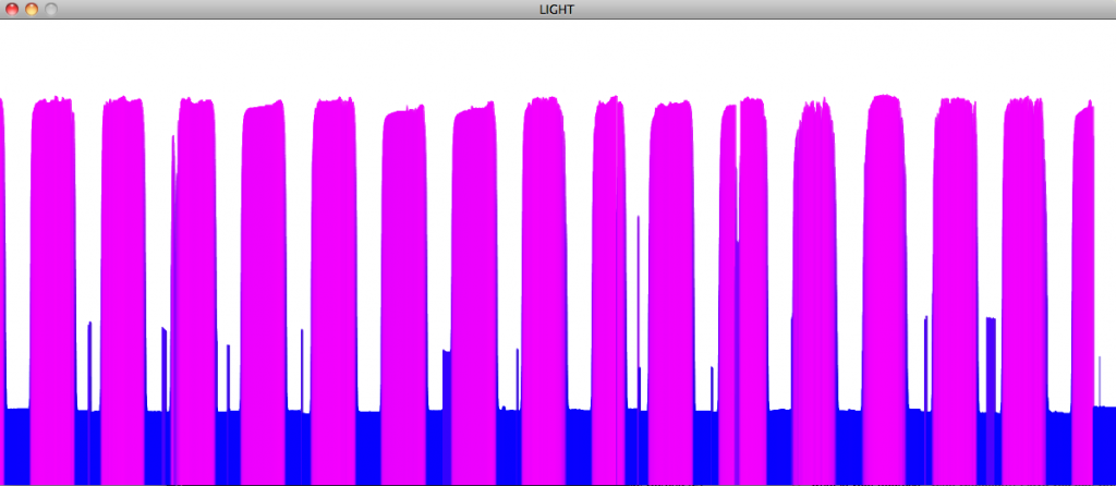
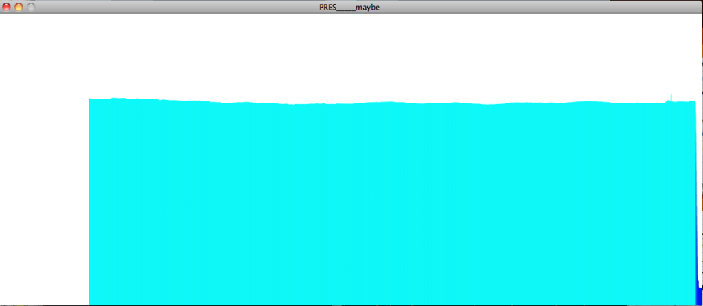
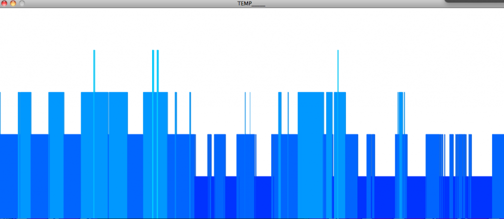
bytelight over time
Some visualizations of the colors of ByteLight over the course of a month

And this is zoomed in on two weeks in May:


Byte Light
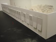
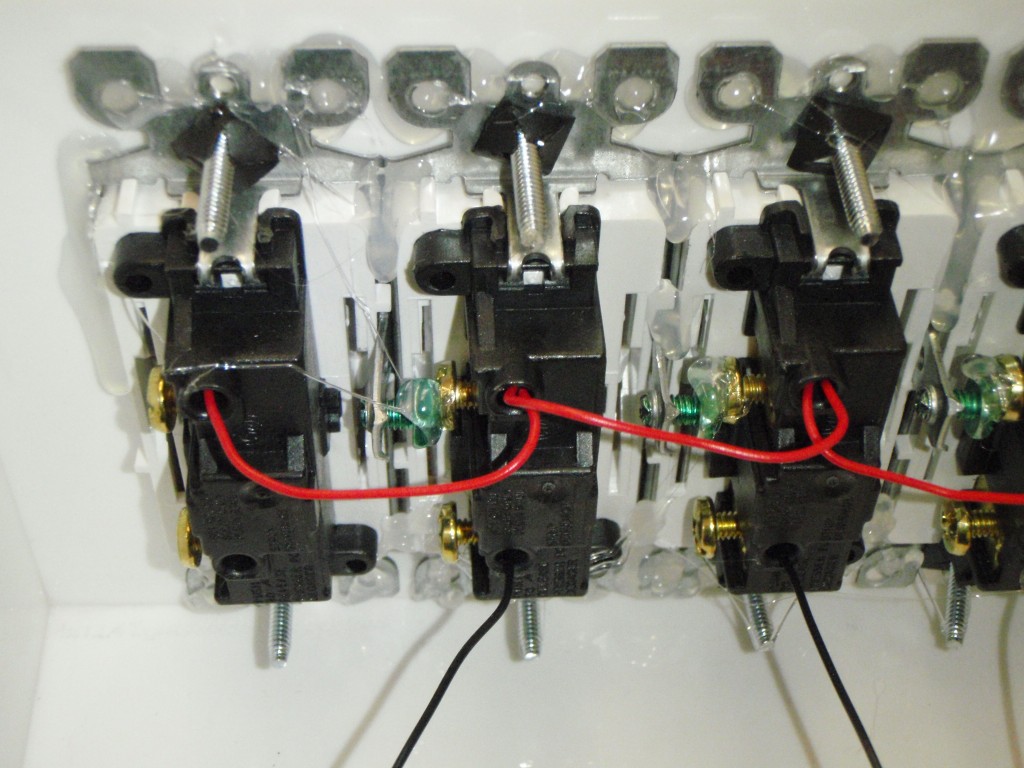
Jack and I collaborated to make ByteLight, which is an interactive light fixture that represents a giant LCD pixel. People can manipulate R, G, and B values of the pixel by flipping on and off 24 switches, which represent individual bits.
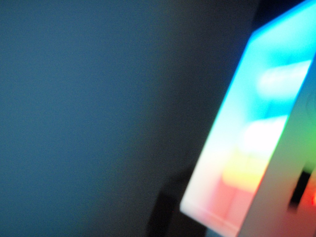
In the video above, someone flips the switches on and off, and watches the ambient light change color. The user can look up at the light fixture and see what happens to individual R, G, and B values when different combinations of switches are enacted, and the projected light color from the mixed R, G and B lights shows the color output of the pixel. It is possible to play and interact in a fun and compelling way, and also to experiment with bit data to gain a more comprehensive understanding.
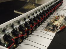
Here are some images from our process:
see here for more
ByteLight update
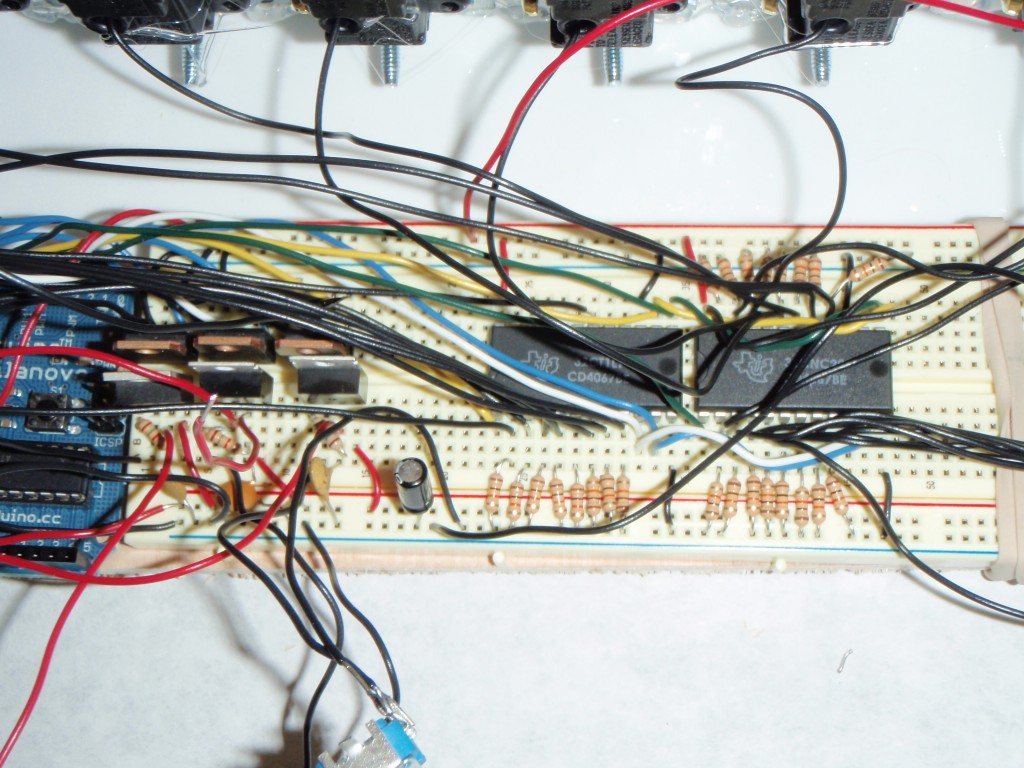
We finished our R, G, and B strips (each with about 45 LED’s), and we hooked them up to the bench power supply. We are feeding voltage through the breadboard, then through both the Arduino V-in, and through two adjustable voltage regulators (LM317) – then through three transistors. One goes to green and blue LED strips, which each ideally require about 3-3.5 V, and one goes to the red LED strip, which requires about 2.5 V.

Here we are testing the lights. It took us a little while to figure out how to get the brightness of each color to be more calibrated – since the red ones require less voltage, we realized we’d need an extra voltage regulator.
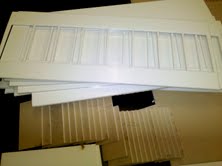
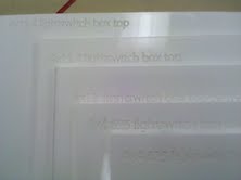
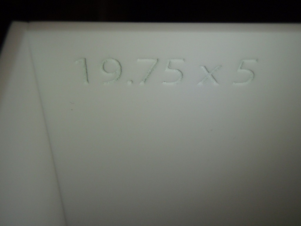
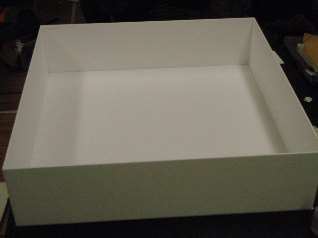
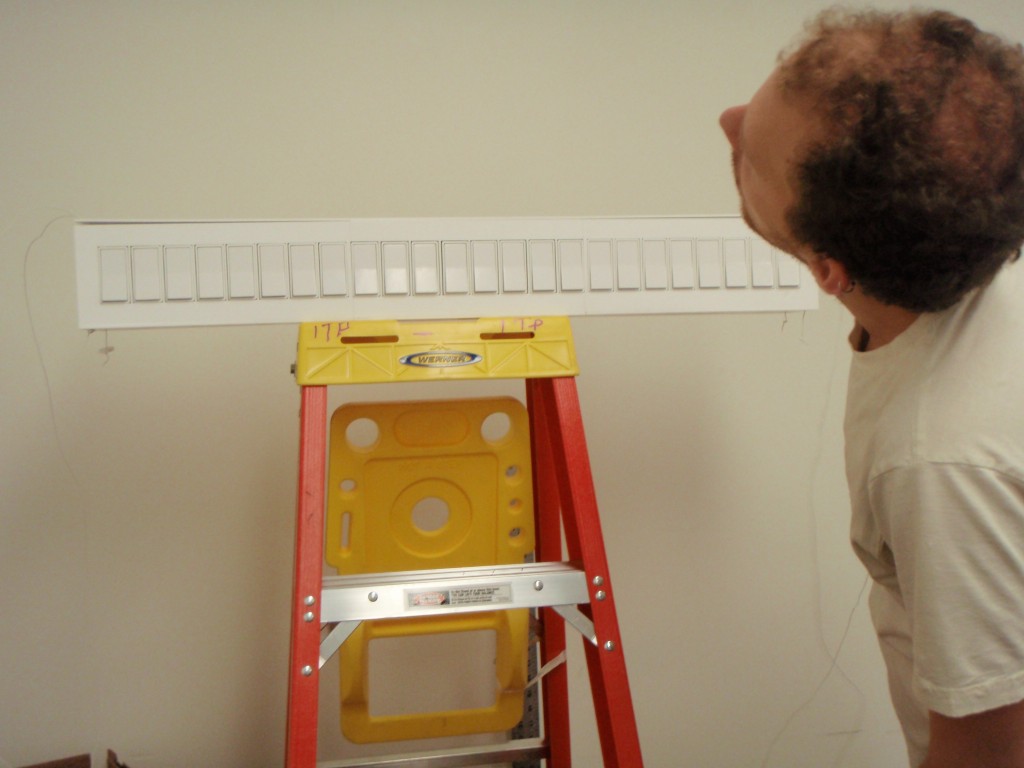
We got white glossy plexiglass which we will sand to look matte. With about 4’x4′ we should be set, although we have much extra. We will use AMS to cut out the parts for the light fixture (a box roughly 20″x20″x4″) and a box to contain all the switches, the arduino, the wiring, and the breadboards (roughly 35.5″x4″x4.625). I made the templates using Illustrator.
269 Canal street is a decent place to get parts. We got a power adapter that goes up to 5 Amps, so we should have enough with that to get the desired voltage and amperage for the LED’s.
Big Pixel – process
see here for older Big Pixel progress links.

Jack and I have continued work with our light fixture, aka Byte Light.

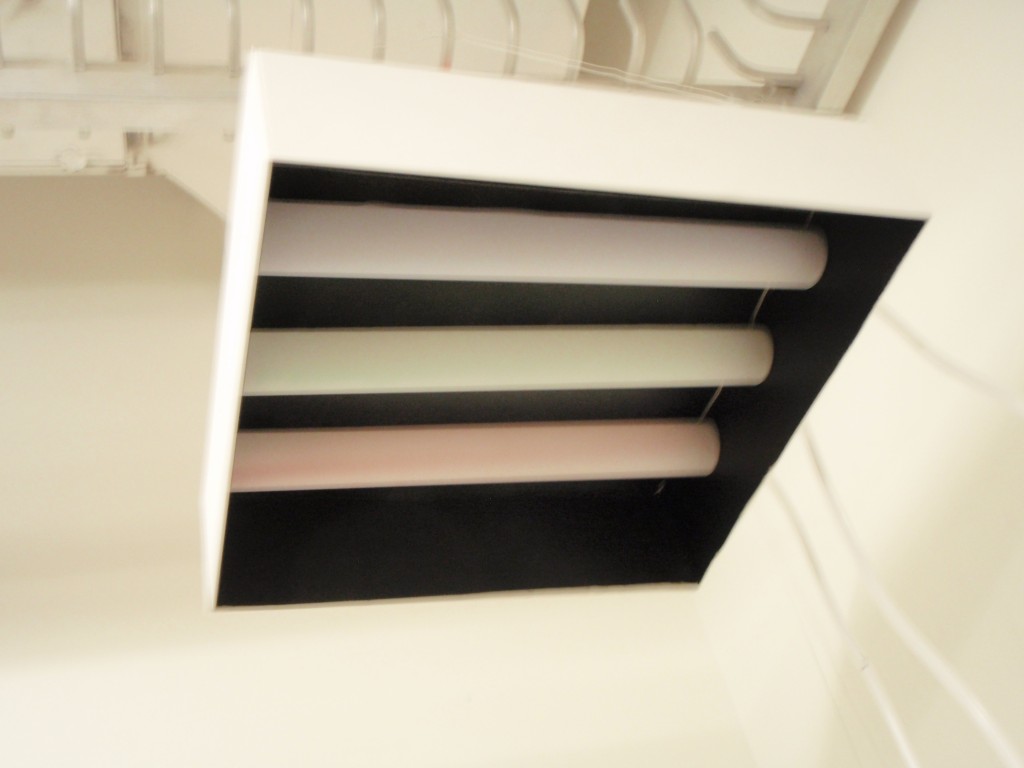
We have soldered 50 red, 50 blue, and 50 green 10 mm superbright LED lights each to three plexiglass rods, which will each represent one of the R, G, and B lines in our LCD pixel representation. Each LED needs 20 mA, and between 2-4 V, depending on the color. Therefore, we need an external power supply that goes up to around 3 Amps (when every switch is on). We will encompass each colored LED rod with frosted paper, and encase the three in a square plexiglass box that will shine light downwards on the user, who will be manipulating the 24 switches on the wall.
Our circuit consists of two multiplexors as input from the 24 light switches. Then the arduino takes the binary input and translates it into byte values (0-255) for R, G and B values, and using three transistors, we will alter the brightness of each R, G, and B light rod.

wall wash pixel from a LCD pixel representation
Screen images bombard contemporary society, yet few people understand how these images are composed.
Jack Kalish and I are collaborating to create a light fixture that represents one giant LCD pixel of RGB color. In order to do so, we are going to use bright three rows of LED’s (one red, one green, and one blue). Each LED row will be controlled, and have 255 distinct brightness levels. The LED’s will be mounted perpendicular to the wall, above head level, and create a wall wash effect. As the colors of each LED mix (and each one has a different brightness level), the light emitted represents the color given off by a pixel that is made up of those three color levels.
![]()

The level of brightness of each LED row depends on the interaction: We are going to set up a grid of switches that a person can interact with to control the brightness of each of the three LED rows. Each switch that a person can control will represent a bit. As a user plays with the switches, he will be manipulating the digital data manually.
For a typical LCD pixel, each byte of the R, G, and B value are made up of 8 bits, so we will have 24 manipulatable switches. The switches represent either an on or off value (0 or 1), and 8 switches determines a value from 0-255 of each R, G, and B value.
By augmenting the resolution of data (each of 24 light switches represent one byte), and the size of the representative pixel, We hope the experience will be immersive, and through playing and interacting with our switchboard, the user will begin to understand how digital data communicates simple signals.

(We were trying to decide what types of lights to use – at first we thought three fluorescent lights would be good, until we realized that dimming them would pose a problem)