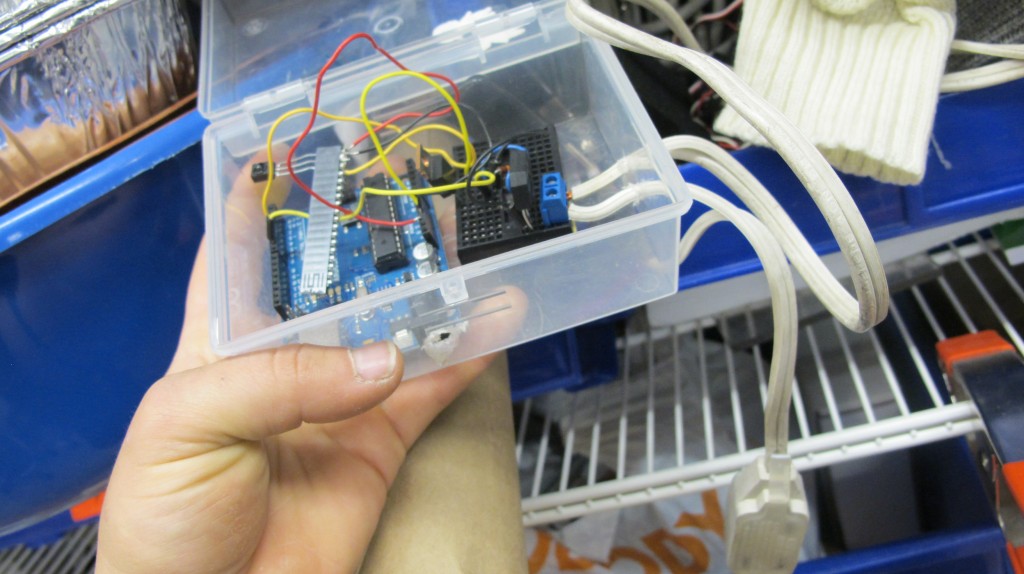
AC DIMMER Circuit!!
I adapted this from info from Dmitri Grinberg’s post on Hackaday, “Lamp Fading and Remote Control for the Lazy”.
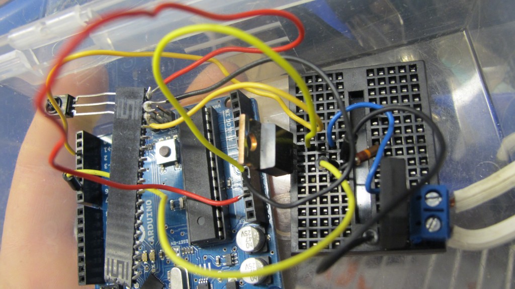
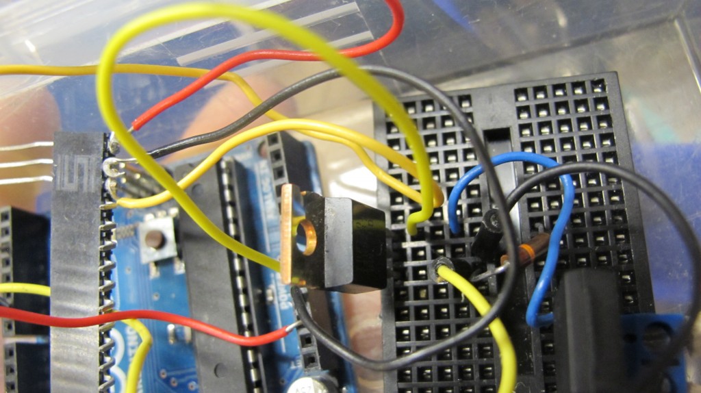
I have been trying for a number of weeks to perfect this, as in, find the correct transistor that would not overheat or burn out (one that is rated for a high enough voltage since it’s using AC 120 V). I followed this circuit from Dmitri’s blog, except instead of the IRF 250 I used an IRF730. 
At first, I was using the IRF 520, with a 100 V drain source voltage and a 9 amp continuous drain current. It worked fine at first, and then it burnt out (there was connectivity between the gate-source and gate-drain). So I got an IRF540, with a 100 V drain source voltage and a 33 continuous drain current. This similarly worked at first, then burnt out.
Finally, I used the IRF730 which works pretty well so far! And doesn’t burn out – it is rated upto 400 V (which far surpasses the 120 V wall voltage in the US).
It works for a light (a resistive load):
and a fan (an inductive load):
Here is the simple dimming code used with the infrared detection sensor. I used a universal sony remote as the transmitter.
2 Responses to “AC DIMMER Circuit!!”
Hi Gabriella,
can this circuit support supply 220vac?
can you post the program in text format for me? i do had a problem opening your attached file.
i am working to do a project similar with you just that i dont want to use IR yet.
thank you..
Hey – yea the IRF 720 can handle over 400 Volts so that will work fine. Without IR you can use any simple PWM output to control the output.
here’s the code I used
#include
IRsend irsend;
int RECV_PIN = 2;
const int RELAY = 13;
const int RELAY10 = 10;
const int RELAY1 = 6;
const int RELAY2=7;
int relayState = 0;
int relay1State = 0;
IRrecv irrecv(RECV_PIN);
decode_results results;
int counter = 255;
long previousMillis = 0;
long interval = 500;
void setup()
{
Serial.begin(9600);
irrecv.enableIRIn(); // Start the receiver
pinMode(RELAY, OUTPUT);
pinMode(RELAY1, OUTPUT);
pinMode(RELAY2, OUTPUT);
pinMode(RELAY10, OUTPUT);
}
void loop() {
if (Serial.read() != -1) {
for (int i = 0; i < 3; i++) { irsend.sendSony(0xa90, 12); // Sony TV power code } } else if (irrecv.decode(&results)) { Serial.println(results.value, DEC); unsigned long currentMillis = millis(); if (currentMillis - previousMillis>interval){
previousMillis = currentMillis;
if(results.value==2894&&relayState==HIGH)
{
relayState=LOW;
counter=0;
Serial.print(“relayState = “);
Serial.println(relayState);
Serial.println(counter);
analogWrite(RELAY10, counter/4);
}
else if(results.value==2894&&relayState==LOW)
{
relayState=HIGH;
counter = 255;
Serial.print(“relayState = “);
Serial.println(relayState);
Serial.println(counter);
}
else if
(results.value==3216&&relayState==HIGH){
counter = counter -20;
if(counter< =0){ counter =0; } Serial.print("dimming "); Serial.println(counter); } else if(results.value==1168&&relayState==HIGH){ counter=counter+20; if(counter>=255){
counter = 255;
}
Serial.print(“brightening! “);
Serial.println(counter);
}
analogWrite(RELAY10, counter);
}
if(results.value==691022&&relay1State==HIGH){
relay1State =LOW;
Serial.print(“relay2State = “);
Serial.println(relay1State);
}
else if(results.value==691022&&relay1State==LOW){
relay1State=HIGH;
Serial.print(“relay2State = “);
Serial.println(relay1State);
}
digitalWrite(RELAY, relayState);
analogWrite(RELAY1, counter);
digitalWrite(RELAY2, relay1State);
irrecv.resume(); // Receive the next value
}
}